This thread has been locked.

If you have a related question, please click the "Ask a related question" button in the top right corner. The newly created question will be automatically linked to this question.

LM34910C -- Suppresses 433MHz Receiver

Other Parts Discussed in Thread: LM34910C

Hello,

I have a LM34910C powering a board that also contains a 433MHz receiver (among other circuitry). Because the range of that receiver was very poor I did further investigations and the culprit is the LM34910C.

I already lowered the LM34910C switching frequency (from 470kHz to 115Khz) and changed its configuration to the low ripple one (adding a resistor and 2 capacitors). Although this somewhat improved the reception it is still not near what I can achieve with the 433MHz receiver mounted on a breadboard.

If I have this "standalone" receiver setup at 1 meter (or more) away from the board with the LM34910C it works flawlessly, however if I bring it to the vicinity of the board with the LM34910C it stops receiving.If I bypass the LM34910C and use a lab power supply, both the standalone and the on-board 433MHz receivers work without a problem.

So, my current idea is that LM34910C is somehow polluting the ground plane turning it into an antenna that kills the 433MHz signal. How can I fix this? Is there some way of isolating the grounds?

Any idea will be highly appreciated.

Best regards,

André

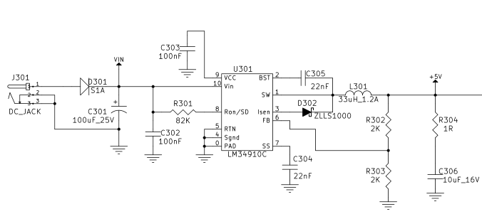
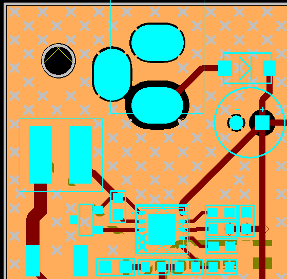
Ps: Attached is the original schematics and board layout.

  • Hi Andre,

    Please provide the SW node voltage, inductor current, and VOUT waveforms. From what I see, the VIN capacitor(C302) is not placed close to the IC with short traces.

    Thanks and regards,

    Vijay

  • I had a similar problem with a power supply a while ago. Not the same chip or circuit , but had the same issues.

    A snubber across the schottky diode fixed the problem. I think it was 2n2 and 4.7 ohm if my memory serves.

    Schottky diodes can be noisy :0)

    Robin

  • Hi Vijay,

    thanks for the reply and sorry for the delayed response.

    The nominal power supply is 48V but it must work with voltages down to 12V. The system current is less than 100mA@48V (~230mA@24V) but it has current spikes that can go up to 1A, they are really hard to measure.

    In the following images the power supply is 48V converting down to 5V.

    Vout with 48V input:

    Vout with 48V input -- 200mV scale

    Voltage on SW with 48V input

    Just to give more data I also have some measurements using a 24V power supply.

    Vout with 24V input

    Voltage on SW with 24V input

    Hope this helps. I already read a lot about this DC/DC converter and any new input will be great to make everything work ok in the next hardware spin.

    Best regards,

    André

  • Hello Robin,

    thanks a lot for your reply. I had read on another post that a snubber on this chip's Isen pin (where the schottky is) could be a good thing to suppress this kind of problems. I have just one question for you, when you say across are you suggesting to put the snubber between both pins of the schottky?

    Best regards,

    André

  • Yes , exactly.

  • Hi Robin,

    ok, thanks for the clarification. I'll try it and see what happens.

    Best regards,

    André

  • Depending on your switching frequency , you may have to fiddle values to optimize the cct.

    I'd start with say 2n2 and 4.7ohm , but I'm sure a little trial and error will come in here :0)