This thread has been locked.

If you have a related question, please click the "Ask a related question" button in the top right corner. The newly created question will be automatically linked to this question.

bq24600 noise throughout system

Other Parts Discussed in Thread: BQ24600EVM, BQ24600

Hi

I have successfully set up the bq24600evm for charging 3x lithium cells with an output voltage of 12.6V: this works really well.

My own circuit design is close but has noise present which is causing the output current to be much higher than the 1.08A it is set to. The noise is present without load. There is no battery connected and the ST LED is flashing as I haven't even got the thermistor connected.

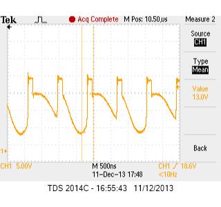
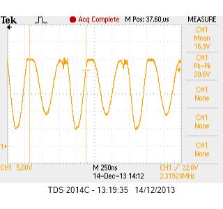
Throughout the system there is noise which looks like ringing every 860ns (1.1MHz) lasting 68ns. This is the same frequency as the gate drive to the high-side FET, so the noise is coming from the LC resonating circuit.

I can see this interference on Vref,  REGN,  LODRV, VCC and BTST. On Vref the noise is +- 2.4V.

The main difference between the EVM and my design is that I am using a two layer board. I have separate ground planes for power and control stage which are connected only at the power pad of the bq24600. I have attached my Gerbers.

I am also unclear from reading the datasheet for the EVM what the BATDRV and ACDRV do exactly. I do not have these circuits in my design as they do not feature in the device datasheet.

Can anyone suggest a sensible way forward. It is frustratingly close to working.

Thanks,

Andy

4786.li_ion_charger_v1_00.zip

  • I have tried changing the output inductance and capacitance, rerouted tracks, changed the groundplane and nothing has any affect on this noise.

    Here is how the HIDRV should look (taken from the EVM):

    This is how my own layout looks: (notice how the gate drive isn't dropping quickly. The input voltage is higher here which explains the shorter pulses.)

    The MOSFET used is: a BSZ097N04LS

    The gate tracks are short. Why would the gate drive not be falling quickly enough? The gate capacitance isn't significantly different from those of the FET's used on the EVM.

    Please help.


  • What is your voltage on the ISET pin and what value of sense resistor are you using?

    For a 10mOhm resistor the gain is 5A/V for the voltage on the ISET pin.  If you want 1A that would be around 200mV on the ISET.

    I did not see an assembly plot so it was hard to tell your placement, but it look organized.  I did not see a lot of vias from the ground of the power components to the ground plane and this helps with noise.

    Do you have the filter shown in the data sheet for the sense resistor.

    The bq24600 does not have power path management and thus on AC and BAT FETs.

  • Hi Charles,

    Thank you for your reply. I am using a 3.3uH inductor, 2x 10uF output caps, and yes, a 10mOhm sense resistor. The two 100nF caps are in place as per datasheet.

    The ISET pin is approximately 240mV. According to the spreadsheet for working out the circuit values and parameters it should be 216mV for 1.08A. It appears close to that value but there is so much noise it is distorting the signal into the bq24600. This is a scope trace:

    Here are the Gerbers with overlays:

    3364.li_ion_chg_v1_00.zip

    May be it just needs more vias?

  • I would make sure your BTST diode is good and installed correctly and that REGn is good.

    What does you switch node waveform look like.

  • Here is the phase-switching node (no thermistor in place and no load). It looks very similar to the EVM:

    I have checked and replaced the diode (BAT54 40V) and no difference. This is the noise on REGN:

    This is BTST:

    This is the gate drives (no thermistor or load connected). This looks very similar to the EVM so possibly not the source of the noise. I am wondering if I need to design this on a 4-layer board.

    I can confirm that the majority of the noise is coming from from the LC circuit. This is a scope trace showing that when LODRV pulses, a large spike appears on Vref. Yellow= Vref, Blue= LODRV

    I have checked thoroughly the circuit and apart from the internal ground plane on the EVM I cannot see any major differences.

    Nothing I do makes any difference apart from one thing: If I set the input voltage to 19.6V the noise reduces. It doesn't disappear but the large spikes are significantly reduced. Any voltage either side of 19.6V and the noise returns. When a load and thermistor are connected the circuit works, it's just noisy. Here are the LODRV and HIDRV signals when a load is connected:

    HIDRV and LODRV

    Any thoughts?

  • I have hacked the board around all day today: changed the ground plane, solid, star, mixture of the two. Nothing makes very much difference. The circuit does work but the noise results in too much current being drawn as the noise is also present on ISET.

    Does anyone have a working two layer design they would be able to show me?


  • Here is my PCB layout. I may have the inductor too close to surrounding components:

  • I would trouble shoot the board with a load on the circuit (charging a battery).  Are you using a high frequency probe (one with a very short ground lead (<0.5").  This will help see what is noise and what is being picked up.

    I not sure you issue is a 4 layer board but it does help having the layer closer together like with a 0.031" PCB.

    Your vias seem huge.  maybe you can put a copper wire in the vias to help carry the high pulsed currents.

    Also try some lower value caps (1uF and 0.1F) taked on top of the higher values caps on the input and output.