This thread has been locked.

If you have a related question, please click the "Ask a related question" button in the top right corner. The newly created question will be automatically linked to this question.

load of LM26780-adj

Other Parts Discussed in Thread: LM2678

Hi,

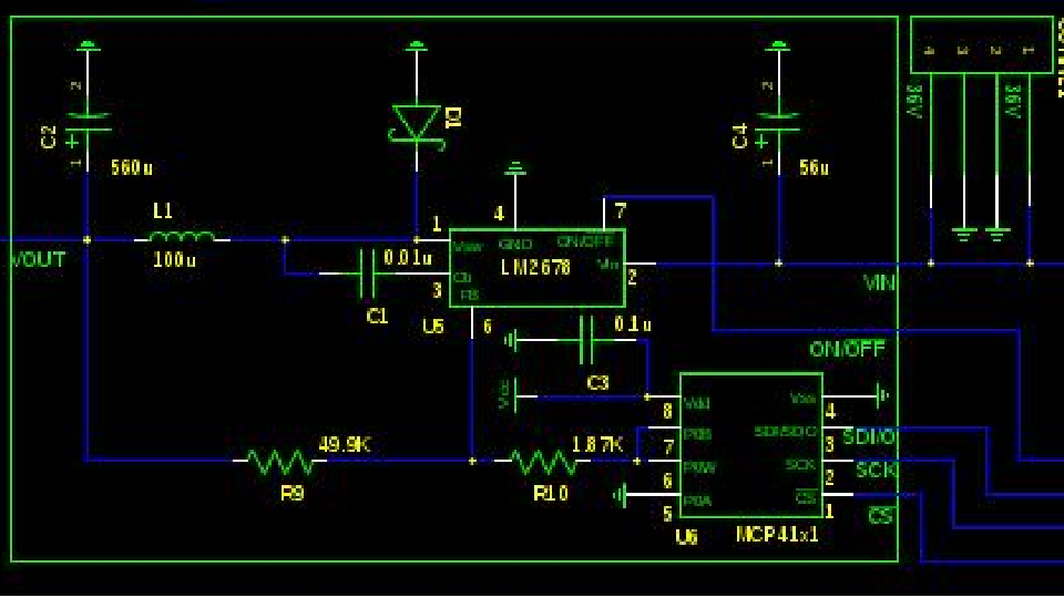
We use LM2678 adj to provide power to 16 loads in our project. The input is 32V, output should be 15-25V. each load has 25W. MCP4151 is used to adjust the resister of feedback, so that the output can change..   But we meet some problems. When there are 2 loads, the output can change from 15-25V. when the number of load increases, the max output voltage  decrease. And the Vfb also decrease. I have try many different output inductor and capacitor. But the problem remains. Please give me some suggestion. Thanks.

  • The current limit may be as low as 5.75 A peak.  For example if you have 15 V output at 25 W, that's 1.667 A per load.  with 100 uH inductor, the ripple current is .354 A and the max load current is 5.75 - (3.54/2) = 5.57 A, so 3 loads are the maximum you can possibly use.  You probably need to look at your inductor rating as well.  You will need to look  at a much higher current rating converter to supply the load current to 16, 25W loads.

  • Thanks, John. 

    I think my former statement is not very clear.  each load in our design actually is a bunch of flashing LEDS (about 120 LED.)  when the output is 25V, the current is about 0.5A for only one load.(so the power should be 12.5W). when the output is 15V, it is less than 0.5A. But when we add three or more loads, the max output voltage decreases drastically, and the max total current is about 1 A or less. And the Vfb is only 0.8 when there are 5 loads, whatever we adjust the MCP,the outpur voltage cannot meet the desired value.

    Because the load flash with very high frequency, does it affect LM2678-adj?  We assume it happens, and add 0.1uf capacitor for each load input to eliminate the interference, but the result has no change. 

    for the  inductor we use, the Isat is about 7A, Irms is 5A.

  • Your problem still sounds like over current.  When the peak switch current reaches the limit the high side switch is turned off reducing teh required duty cycle for proper regulation.  This causes the output voltage as well as Vfb to decrease. 

  • Thanks, John,

    If so, do you have other solutions? Should we choose other chip?

  • I suppose you should verify that current limit is in fact your real issue, not something else.  I just pointed out that it is very possible based on your symptoms.  I have to tell you that I do not directly support that product line, but I often answer posts if I have a something to contribute.  You could use the Webench design tool to look for possible solutions by entering your input and output requirements.  let me know what you find out.