This thread has been locked.

If you have a related question, please click the "Ask a related question" button in the top right corner. The newly created question will be automatically linked to this question.

PCB Design Verification required for Gas Gauge "BQ27541"

Other Parts Discussed in Thread: BQ27541

Hi,

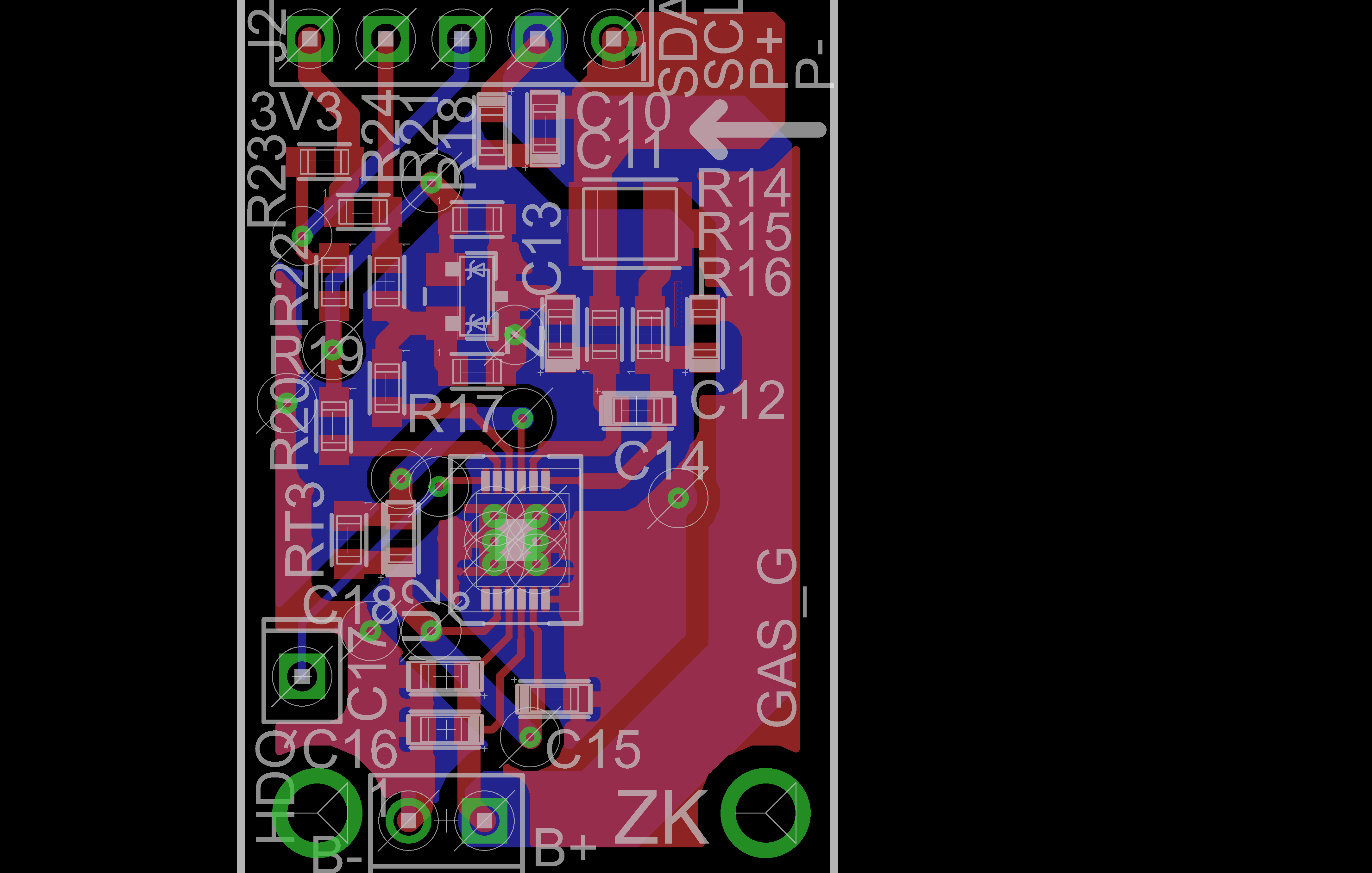
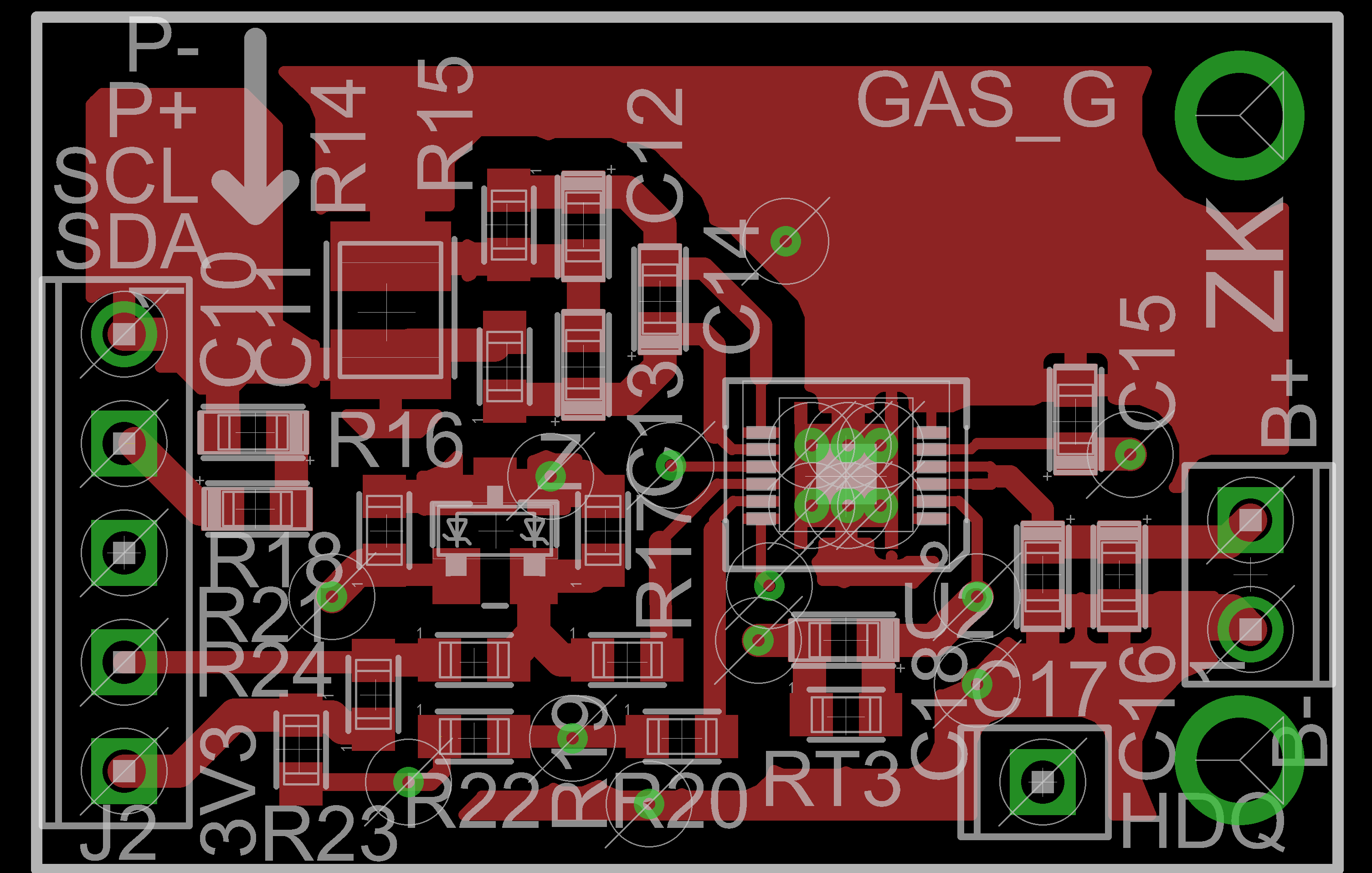
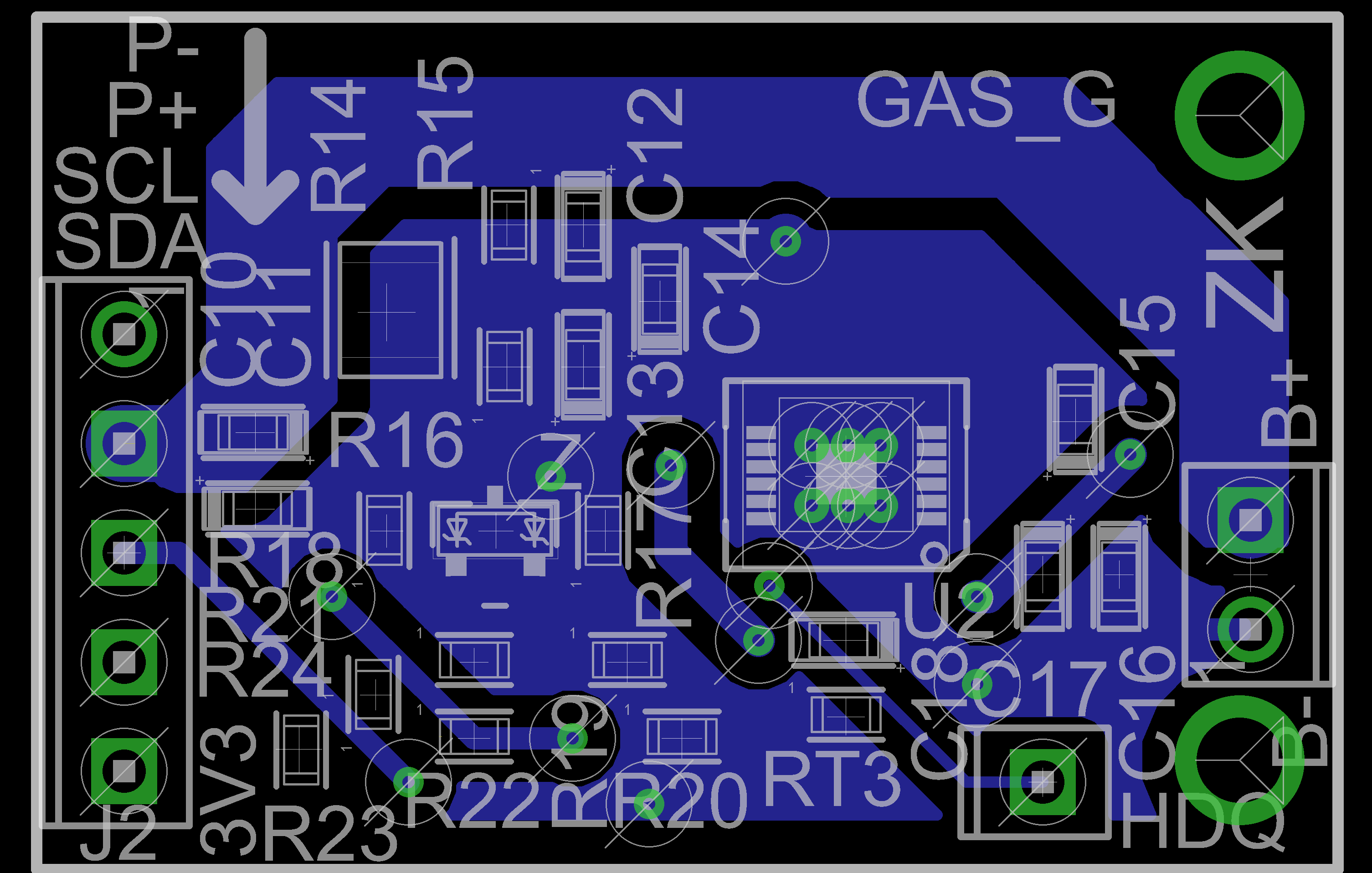
We are using BQ27541 gas gauge IC for our battery application. I have referred TI evaluation layout design for our new design which is shown below. So please check and verify the design and Let me know any changes required for our new design. So that we can give it for PCB manufacturer.

Regards,

Naveen K

  • Hi, Naveen,

    The schematic design:

    1. it is good, however,  It might be no so safe for battery pack without protector IC and NFET.


    The layout design:

    1. C12 and C13 should connect to Ground with symmetrical layout
    2. C16 and C17 should connect separately to Pin BAT and Pin REIGN for decoupling
    3. It is better to place RT3 close to battery

    You can find the detail information from the attach file. 8244.bq27541_board-design_checklist.xls

  • Thanks for you advice.

    We have battery with inbuilt protection circuit. So i think its not necessary to add externally right?

    1.I have modified the design as per your suggestion please check and advice

    2.I have modified the design,but i have doubt here. In EVM design C16 and 17 is shorted pls check it with bellow image and advice which one is better?

    3. noted 

    Regards,

    Naveen K

  • Actually, decoupling is a method to prevent undesired coupling between subsystems. In the core of IC, Pin REGIN and Pin BAT connect to different IP-cores separately. 

    If voltage regulator in the IC core being pulled down by the momentary current load, it is better to have a separated decoupling capacitor to prevent the coupling to another .

    So connection in the EVM is unable to decoupling properly. The layout of EVM might be a good way to design your board, however it can always be improved somehow.