This thread has been locked.

If you have a related question, please click the "Ask a related question" button in the top right corner. The newly created question will be automatically linked to this question.

bq24600 HIDRV

Other Parts Discussed in Thread: BQ24600

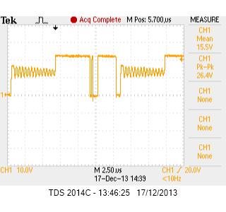
I have a bq24600 working and charging on my own board. All voltages seems OK and the current draw is good (1.2A). However the HIDRV looks like this:

BTST goes to 6V when LODRV is on so the bootstrap cap and schottky diode are working.

I have the EVM which works fine with the same configuration: i.e. square wave.

What would cause the HIDRV to do this?

  • Put a loop of wire in series with the inductor and use a current proble to measure the current.

    It is probably going discontinuous.  Try raising the input voltage or increasing the charge current.

    What is your input voltage and battery voltage and charge current?

  • Battery voltage: 11.1V (3-cell)

    Output voltage set to 12.6V

    Charge current: 1.08A (216mV)

    I have just decreased the input voltage from 16V to 14.28V and it has started working perfectly.

    So reducing the input voltage solves the issue, but I do need to run from higher input voltages.

    Does this mean it is related to the duty cycle? Will increasing the charge current help in this case?


  • What inductor are you using?

    Look at the inductor current?

    Maybe try the EVM inductor on your board.

  • Are you using a real battery or a battery simulator?  If there is any issue, alway try a real battery and see if that helps.

    Charging and termination present transient issues for electronic loads and sometimes they interact where a battery will not.

    what happens if you lower the battery voltage?

  • I am using a real battery after reading other posts on issues with simulators.

    The inductor is identical to that used on the EVM. Same part number. I have also tried using a 3u9 instead of the 3u3 but it makes little difference.

    This has completely stumped me. As the battery voltage is lowered the current consumption on the PSU increases to way above what ISET is set to. I have had this issue on two boards now so I don't think it's a bad solder joint.

    As the input voltage is increased on the EVM, the current drops as you'd expect: same power. 

    I do not have a current probe to hand for measuring the inductor current. I will have to source one.

    It is so close to working but something is not right.

  • I can confirm that the BQ24600 is going into discontinuous mode above an input of 14.6V. This mode then causes the current consumption to rise: this is not the current to the battery, just from the supply. The only difference between my application circuit and the EVM are board layout and FET's. 

    I am wondering how much difference the output capacitance of the MOSFETs makes to the switching circuit. I am using FET's (Infineon BSZ097N04) with 340pF output capacitance compared to 185pF of the SiR426DP as used on the EVM. Otherwise the BSZ097N04 outperforms the SiR426DP. 

  • would you please attach a schematic and also a scope shot of the inductor current.

    The increased output capacitance will increase the switching losses slightly.

  • Hi,

    Just to conclude this post: I have prototyped this circuit on a redesigned PCB and it all now works very well. The main difference is which switching FETs were used. My new design uses the same FETs as the EVM: SiR426DP. My original solution used more modern devices with better performance: BSZ105N04 but I suspect this was the reason something was off. I am going to investigate out of curiosity.

    Thanks

    Andy

  • Let me know what you found out!