This thread has been locked.

If you have a related question, please click the "Ask a related question" button in the top right corner. The newly created question will be automatically linked to this question.

LM3447 Startup

Other Parts Discussed in Thread: LM3447

Hello!

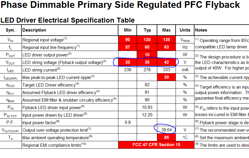
I'm trying to track down an intermittent problem we are having with the LM3447 on a new design.  When we power the board from 230V from a non-dimmed source, occasionally the light flashes and does not appear to startup correctly.  Attached is a scope shot of the VCC pin using a voltage probe with a 50:1 gain.  The peak appears to be getting close to 17.7V.

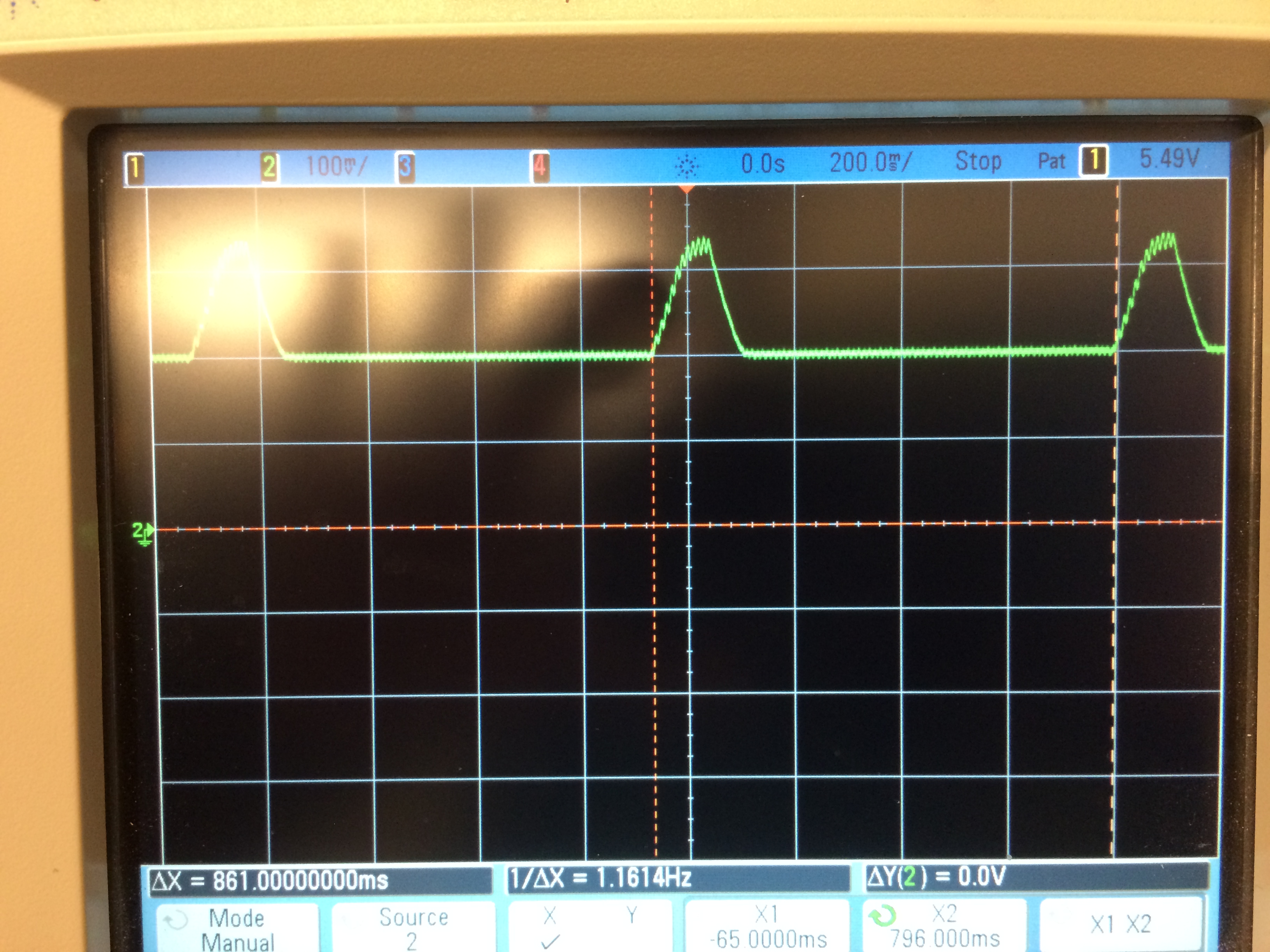
It happens occasionally when we operate the light at room temperature, but we can get it to happen more consistently when we operate the light at 0C.  The 120V of this board seems more reliable.  Does this appear to be an over voltage condition?

Any feedback or input on this is welcomed and appreciated!

Thanks again!

Paul

  •  We are now wondering if it is output overvoltage protection that is triggering.  We wanted to check this by probing the AUX pin, but as soon as we attach a lead to this node the board completely stops working.

    We've been reviewing our selection for the AUX resistors compared to the calculations in the spreadsheet design tool that was downloaded from TI.  On the Inputs tab, there are fields for Min, Typ, and Max for Vout.  Further down the sheet, the Vout field is calculated for you.  What we find strange is that the Vout calculation is lower than our input Max string voltage that we entered.  The calculation is using the Minimum string voltage to calculate the set point.  Is this correct?


  • The design spreadsheet calculates the auxiliary turns ratio based on the minimum LED string voltage entered in the "input" sheet.  This is to ensure that sufficient VCC voltage is generated to support circuit operation in steady state As a result, the minimum LED stack voltage is also used in calculation of the OVP threshold voltage. 

    The spreadsheet tool provides a general design guideline and may not be suitable for wide range of output voltages.  I request you to refer to the datasheet for exact design equations.  In this case, the problem can be resolved by calculating the appropriate auxiliary winding turns ratio using:

    Na = VCC/Vout*Ns (page 22 of LM3447 datasheet)

    For this application, VCC voltage should be limited to 17V at max vout voltage of 42V. Suitable Na can be derived.  This will prevent false tripping of OVP during nominal operation. It is possible to trick the design spreadsheet by iterating the minimum LED voltage stack specification until OVP threshold voltage is greater than maximum LED stack voltage. The turns ratio on "Xformer" sheet will then provide suitable auxiliary winding turns.