This thread has been locked.

If you have a related question, please click the "Ask a related question" button in the top right corner. The newly created question will be automatically linked to this question.

LM3410 feedback issue

Other Parts Discussed in Thread: LM3410

I have a LED Driving (Boost) circuit involving LM3410 for driving high intensity LEDs with a forward voltage of 6.4V and a forward current of 500mA.

I would like to the know the impact, if the load (the LEDs) gets disconnected from the driving circuit (say, due to user negligence), which could cause the feedback to the driver IC to be pulled low (since I have a limiting resistance connected to ground and in series with the LEDs).

As per the datasheet, the range of the feedback voltage is 178mV - 202mV.

Hence, what shall be the impact, when:

 - The Feedback voltage is pulled low.

- The Feedback voltage is higher than the upper limit of the feedback voltage range.


Please clarify.

  • Hi,

    Thanks for your questions.

    As I found in the data sheet of LM3410, when an LED fails open, or is connected backwards, an output open circuit condition will occur.

    - The Feedback voltage is pulled low.

    The LM3410 will react by increasing the duty-cycle, thinking the LED current has dropped.

    According to the equation in the data sheet, Vout/Vin=1/(1-D), the output voltage will increase.

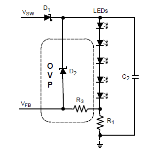
    As you can see in the above figure, “if the output voltage exceeds the breakdown voltage of the zener diode, current is drawn through the zener diode, R3 and sense resistor R1. Once the voltage across R1 and R3 equals the feedback voltage of 190 mV, the LM3410 will limit its duty-cycle. No damage will occur to the LM3410, the LED’s, or the zener diode.”

    - The Feedback voltage is higher than the upper limit of the feedback voltage range.

    Basically, open circuit condition will not cause the FB voltage  higher than its upper limit.

    I can help to check where the 178mV-202mV range comes from if you want, but if you have some concerns about what will happen after the load (the LEDs) gets disconnected from the driving circuit, I think the above answers may help.

    Please check the LM3410 data sheet pg. 7 & 13 for detail information.

    Thanks.

  • Hello Victor,

    Thanks for your response.

    As you had mentioned, I am just curious to know about the 178mV-202mV feedback voltage range and how do we select an appropriae value for R3.

    Based on our working scenario, the load (the LEDs) forward voltage is 6.5V maximum and with a maximum current of 650mA. We would like to know the behavior of the LED driver when the feedback voltage is low (say pulled down to ground through the limitng resistance).

    Also could you please let us know how the LED Driver varies the Duty cycle with respect to the variation in feedback voltage?

    Thanks,

    Santhosh. 

  • Hello Santhosh,

    The typical value of feedback voltage is 190mV and there is a ±12mV margin for process variation. What you should do is to select a suitable R1 to make sure the R1*Iout is in the range of 178mV and 202mV. For your case, a 0.3Ohm sensing resistor should be fine.

    What if the feedback voltage is pulled down to ground? The IC will increase the duty cycle which will increase the output voltage because the IC thinks the output current has dropped (VFB = R1* Iout).

    Since LM3410 is a constant current converter, the output current won’t have significant change in normal condition expect for output short circuit and open circuit. You can’t protect the inductor and diode when output short circuit happens as the Vin is connected to the output load directly. But output over voltage protection can be achieved. As I mentioned early, the OVP circuit consists a zener diode D2 (for your case, an 8V zener diode should be fine) and R3 (100Ohm is OK, too small is not recommended).   

    For the last question, the duty cycle will decrease if VFB increases and vice versa. But there is a limit of the duty cycle. You can refer to the data sheet for the values.

    Please let know if there is anything that I haven’t make it clear.

    Regards,

    Victor

  • Hi Victor (or other TI support).

    I am looking at a design with similar output OVP requirements.  So, in the example above with 8V zener and 100 ohm series resistor what would be the current that needs follows thru the zener diode for regulator to stop increasing the output voltage.  

    I thought 500mA is needed so that the FB pin gets to 190mV but total current is limited by 100 ohm series resistor?

    thanks!

    Sadry