This thread has been locked.

If you have a related question, please click the "Ask a related question" button in the top right corner. The newly created question will be automatically linked to this question.

TPS62125 minimum current

Other Parts Discussed in Thread: TPS62125

Dear all,

I'm using TPS62125EVM to evaluate the use of this chip in my application.

my power supply is a generator with low currents. the voltages are 5V - 10V and the currents are 30mA to 90mA.

I use the output of the chip to charge with 4.1V a small Lithium battery.

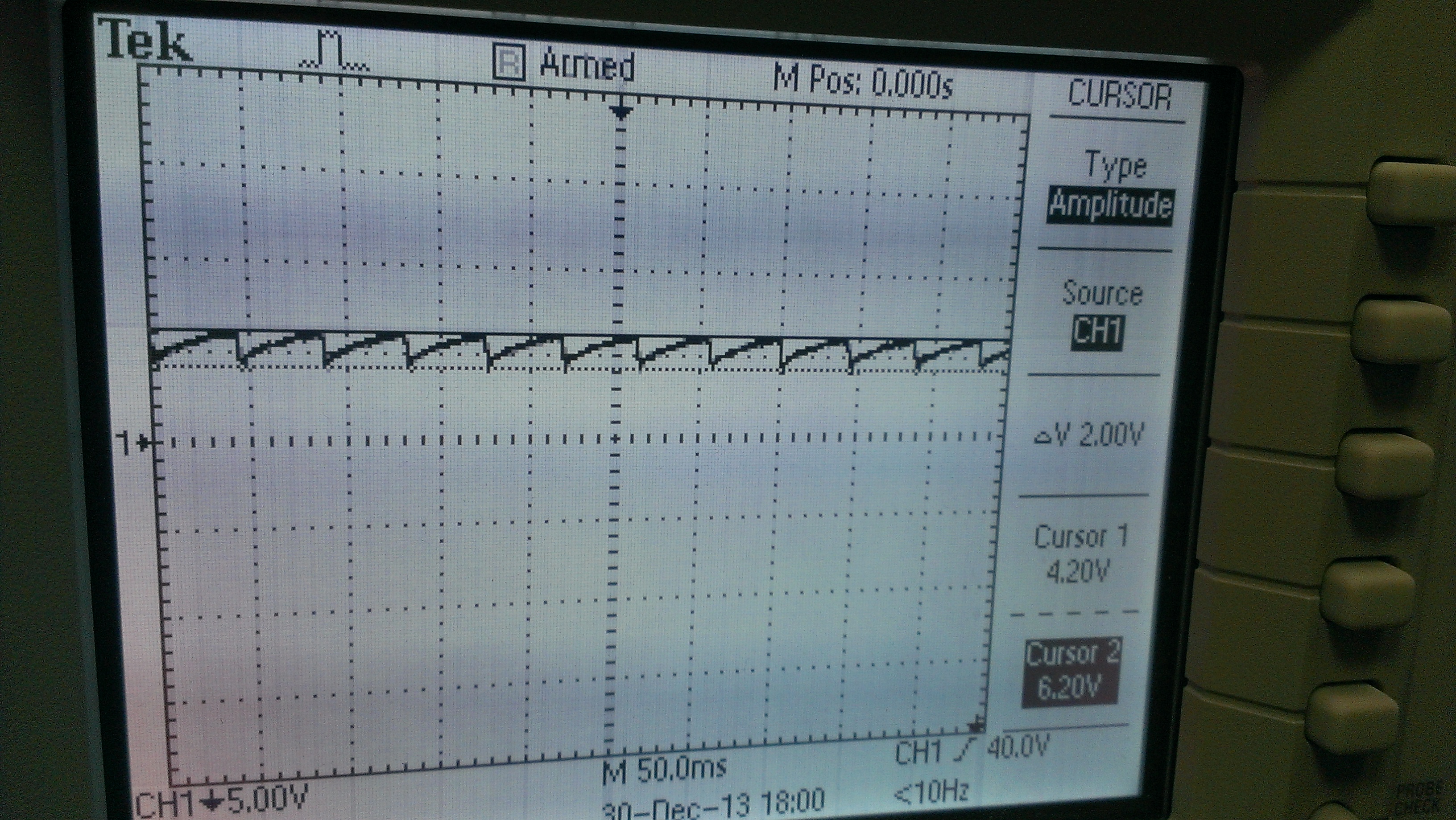
I noticed that every current under 250mA causes the chip to go inside osculation and does not function.

why does it happen? is there any way for me to use this chip, I really like his Iq data.

if not, what can I use instead (keep in mind the low input current).

regards,

  • Could you attach a schematic of any changes you made to the EVM as well as the jumper settings?

    Also, could you provide a waveform of Vin, Vout, and SW that shows your concern?

    Is there a charger between the TPS62125 and your battery?

    Finally, could you provide the VI curve of your input supply?

    The battery is likely drawing more current than your input supply can provide, which crashes the input bus.  This can be overcome on this IC, with these types of circuits: http://www.ti.com/lit/an/slyt478/slyt478.pdf and http://www.ti.com/lit/an/slyt488/slyt488.pdf

  • When you say "go inside oscillation" what do you mean exactly?  Can you post waveforms that show your concern?  Did you modify the EVM at all?

  • Dear all,

    from the EVM point of view:

    1. I changed the EN resistor devider to be between ~4.3V to 6.3V (JP1 is open)
    2. change FB loop to get ~4.1V on the output.
    3. PG is tied to Vout through a 100Kohm (J7 is open is open, and JP2 is shorted)

    when I say oscilation I mean the voltage is constantly changing down an up, I attached a scope image where you can see the voltage dancing around between 6.2V and 4.2V.

    the input supply is simply a power supply on 7V and limited to anything less than 280mA causes this phenomena.

    there is no charger IC since I couldn't find ant charger IC that will accept less than 100mA in his input.

    a quickly looked at the files you attached, I just wanted to say before going any deeper into them, that I want the IC to always deliver the maximum current it could give while maintaining it's steady voltage.
    is this possible by one of the 2 ANs?


    thanks so much for your assistance,

    Ran

  • I think it's worth reading those 2 ANs as they directly apply to what you will be doing.  Your Vin waveform matches what is achieved with those circuits, which is delivering the most power possible to your load with a power limited input source.

    Without a charger, you seem to have a lot of work to do at verifying your design is safe, charges the battery properly, etc.  

    As a side note, I don't think Iq is really critical for your application (see http://www.ti.com/lit/an/slyt412/slyt412.pdf), but the precise enable threshold does make your application possible.

  • Dear Mr. Glaser,


    thanks for the help,

    thanks for the Iq information, it has a very big value.


    from what I see in the ANs a much larger bulk capacitance (something like 300uF) and setting up the EN thresholds.

    although I can't imaging selecting a different values than 6.08V and 4.37V.

    my question is:

    the AN refers to a peak consumption of (let say) a sensor. when the pulse length of around 15ms.
    my system charges a battery that will consume what ever the power source is limiting it to with almost indefinite time.
    how would I calculate the Bulk Capacitance in this case?

    would you recommend a different approach for this application? LDO or Zener circuits?
    thanks,

  • It really depends on what kind of power source you have.  If it has a maximum power point, then you would want to operate in that region always in order to get the most power from it.  The EN thresholds on the TPS62125 would then be set for this.  The bulk input cap is then selected to store enough energy to start the TPS62125 and operate it for some selected time.  For your application, I don't think its value is very critical as you will be charging your battery with bursts of power--always drawing as much from your input source as it can deliver.

    If it is basically a constant output power source, then a battery charger with input voltage DPM would be simplest.  Battery charges with this feature charge the battery with whatever current they can get while keeping the input voltage above some threshold to prevent brownouts.  You could post in the battery charger forum to see if they have a good device for you.

  • Dear Mr. Glaser,

    nice idea with the DPM circuit, but the problem here is the current rather than the voltage, the ICs won't accept less than 100mA...

    about my input,
    it is a rectified AC signal from a generator, that supplies a relatively steady power of 6-12V and 30mA to 100mA.
    the signal is very long, it can be 2 hours sometimes... and the battery will always take whatever current it can take.
    so if I understood correctly, the bulk capacitance here will not aid. since, it is not a case where the battery have peaks of power consumption such as a transmitter of a sensor that transmits every few hours for 15ms.
    here the battery acts as a power bank that operates through a different regulator the transmitter.

    any idea here?

  • You can still pursue either of my ideas from the last post.

    I believe you may be misinterpreting the battery charger's specs.  It may be that you can't set the charging current less than 100 mA, but this isn't a problem for your application since you will always be operating in the DPM region, where the limit is not the charging current allowed but rather the input voltage.  You should confirm this in the battery charger forum.

    Or you can still use the TPS62125 with a bulk input cap and charge your battery in bursts.  This will still deliver the same amount of power as if it were charger continuously (at a lower rate) since power is stored in the input cap.