This thread has been locked.

If you have a related question, please click the "Ask a related question" button in the top right corner. The newly created question will be automatically linked to this question.

LM3150 problems

Other Parts Discussed in Thread: LM3150

I have received a pile of boards back that I had made for prototypes.  I had them made in two batches. The first tested boards worked fine so I had more made to the same spec. 

My problem the second batch exactly the same so far do not work. 

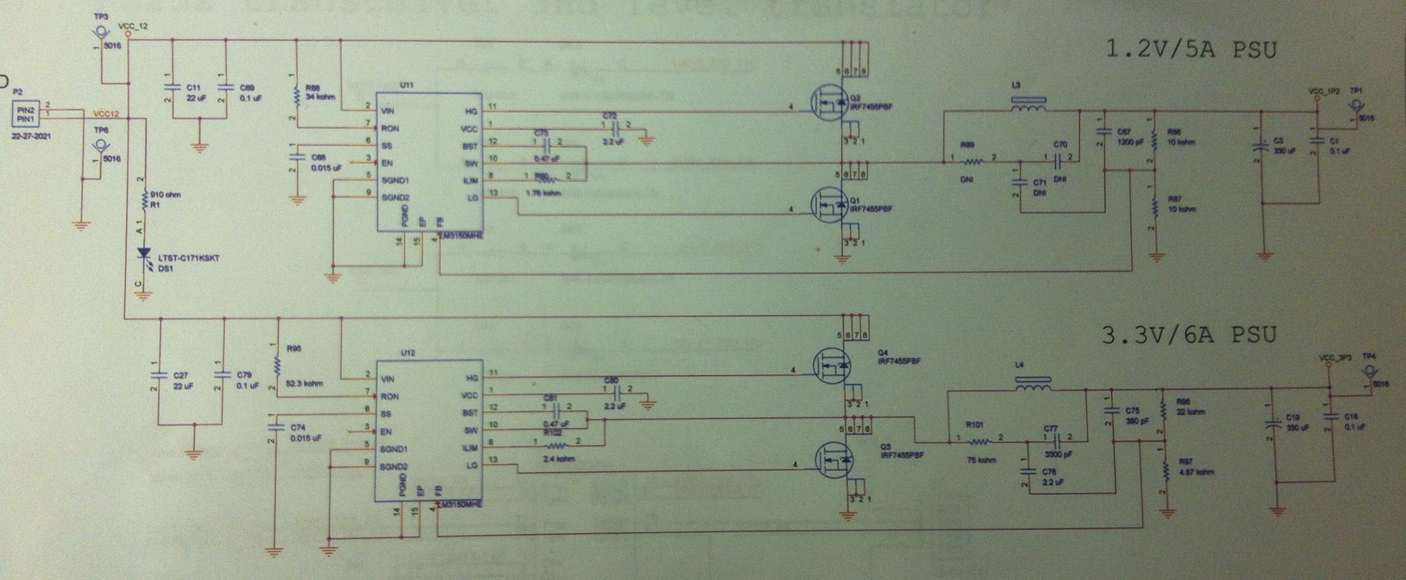
Each boar dis a variation on a devboard and is laid out very similarly. It uses 4 layers signal top and bottom with planes infilled.  Inner GND and split 12v  and output.

I have 2 LM3150 circuits providing 1.2v and 3.3v. Currently only supplying 200ma but the FPGA and external circuitry can take more. 

The 1.2v works correctly on every single board. The 3.3 v only works on the first batch.  both are nearly identical. 

All second batch boards oscillate after 6v in and as I raise the voltage the voltage starts to drop....

I have not changed the component types, manufacturer or supplier. Both batches were bought at the same time .

Can any one explain what could be the problem? It is very frustrating since I have a lot of working boards.

Most of the board is planes so very few thin tracks. I cant find any issues with connectivity so far.

Im using a pair of IRF 7455s with each 3150. AS you can see the IRF devices are very close to the switchers on the opposite side of the board with large planes feeding 12v in , 3.3 and 1.2v out and interconnections.  The 1.2v works on all boards but the almost mirrored 3.3v does not. Frustrating and a pain for a development team. Big contracts depend on this. 

Kind Regards

Robin

  • Here is my schematic.:

  • Hi Robin,

    I apologize for no one seeing your post earlier.  Are you still having problems with the 3.3V Rail?

    The first thing I notice is you have a CRC network across the inductor in the 3.3V system that is not in the 1.2V design.  Have you tried removing this network?

    I will take a close look at the schematic and see if I see any issues.


    Regards,

    Marc


  • Also wonder what that CRC network is for? Have never seen anything like that before across the main inductor on DC/DC converters. Chances are everything will start working good once you remove the network.

  • Hi, thank you for your responses, I have in fact got it working now. 

    One board fault was a fabrication fault the rest were the txco inserted the wrong way round. 

    no consumption up to 0.7v then it conducted heavily and pulled the 3.3v supply down which oscillated. The txco had no markings on once vapour phase soldering was complete so difficult to place. The assembly company assumed it was a normal crystal too. They bought new ones and have fixed it since. 

    I need to sleep now but ill post a bit on the rc net tomorrow if  I have time. if anyone has more info on the components by the indictor from a different perspective id  be interested to hear though.

    Kind regards. 

    Robin 

  • Hi Robin,

    Glad to hear everything is working now.

    In response to the other Customer on the CRC network.  The RC emulates the ripple current from the inductor if you set the time constant correctly.  Then you inject this into the FB with another Cap.  As the 3150 is a variation of a constant on time part it needs some ripple information to get a consistent switching frequency.  So adding the CRC  allows you to run the part with lower ESR capacitors.


    Regards,

    Marc