This thread has been locked.

If you have a related question, please click the "Ask a related question" button in the top right corner. The newly created question will be automatically linked to this question.

Problem BQ25504 Charger thresholds

Other Parts Discussed in Thread: BQ25504

Hello TI Community,

I’m using the BQ25504 as an energy Harvesting Module with a solar cells. For this I’m using the circuit like Figure 2 in the Datasheet. The thresholds are:


UV = 2,4V

OV = 3,5V

Vbat_pog = 2,7V

Vbat_hys = 3,3V


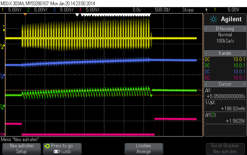
In the first step everything is ok. The circuit has no load and the Boost Converter Charge the battery Capacitor up to 3.5V and Vbat_OK Pin get high. If the Circuit gets a load on Vstor the boost converter charge the battery capacitor and the Vstor capacitor up to 5V. Then it is switch off till 3.5V in Vstor is reached an it charge it up to 5V.


Have anybody an idea what the problem could be?


Best regards

Sebastian

  • Is the load pulling VSTOR below 1.8V?  If so, the cold start circuit may be turning back on.  The cold start circuit is an unregulated boost converter and can cause VSTOR to overshoot briefly before the main boost charger and its OV circuit re-engages.  Is it possible to use VBAT_OK to disengage the load until VSTOR is above 1.8V?

  • Hello Jeff,

    no the load dosen't pull the Vstor below 1.8V.  First the Vstore Voltage is 3.5V then the load will be connectet and then Vstore is charged up to 5V. It Looks like the thresholds are unregarded.

  • Can you take a scope shot of VSTOR and the switching side of the inductor, showing VSTOR rising from 3.5V to 5V?  I want to confirm that the IC is actually switching when the load is attached.

  • Hello Jeff,

    enclose a scope print, showing VSTOR rising from 3.5V to 5V.

    yellow line = switching side of the inductor

    blue line = Vbat

    green line = Vstore

    red line = VBat_OK pin

  • When you installed the Megaohm+ resistors for the various resistor dividers, did you remove all solder flux from the board?  If not, can you replace the Megaohm resistors with 100x smaller size and see if the problem repeasts?  The only time I have seem a similar issue is when the resistors are not at the sizes I expect due to the explanation below:

    During board assembly, contaminants such as solder flux and even some board cleaning agents can leave residue that may form parasitic resistors across the physical resistors/capacitors and/or from one end of a resistor/capacitor to ground, especially in humid, fast airflow environments. This can result in the voltage regulation and threshold levels changing significantly from those expected per the installed components. Therefore, it is highly recommended that no ground planes be poured near the voltage setting resistors or the sample and hold capacitor. In addition, the boards must be carefully cleaned, possibly rotated at least once during cleaning, and then rinsed with de-ionized water until the ionic contamination of that water is well above 50 Mohm. If this is not feasible, then it is recommended that the sum of the voltage setting resistors be reduced to at least 5X below the measured ionic contamination.

  • I have replaced the resistors in my circuit.

    Now the bq25504 charge the sorage up to 8V and this kills the bq25504. It makes no diffrence if a load is connectet or not

  • Did you replace with >1Megaohm resistor or resistors in the <100kohm range?  Using smaller resistors that will not be as affected by parasitic resistances from solder flux will confirm that is the problem. 

  • I have replaced them wis resistors < 100kohm.

    as example:

    Vbat_OV was --> Rov2 = 4,6Mohm ; Rov1 = 5,3Mohm ---> Rges = 9,9Mohm

    Vbat_OV is --> Rov2 = 46kohm ; Rov1 = 53kohm ---> Rges = 99kohm

    9,9Mohm / 99kohm = 100  <-- nominee divider

    should i only use a divider off 10 ?

  • The reduced resistors are good.  Solder flux residue is not the issue.  Keep in mind that the VBAT_OV is only sampled every 64ms.  Is the load you are applying on VSTOR a pulsed load that is faster than 64ms?  If so, then it could be that the load transient is hitting just before the last VSTOR sample, causing VSTOR to droop, but then the load transient ends before the next sample.  If that is the case, then I suggest increasing the VSTOR capacitor to better handle the load transient.

  • The load i have connectet is an linear none pulsed load.

    But with the less resistor ist dosent matter if an load is attached or not . The Vstore and Vbat rise up to 8V which kills the bq25504.

    With the old loads >1Mohm on startup and no load is connected the bq25504 keeps the conditions. Only if a load is attached the Vstore rise up to 5V  and the bq25504 dosent respect the adjusted thresholds.

  • Is this on an EVM or on your board? If on your board, are you certain that the VBAT_OV resistor network is properly connected to the RDIV and OV pins?   Is the load a simple resistor?  Is it possible that the load itself is raising the voltage with current backflow?   

  • The curcuit is on my own board, build in thd technology for test purposes. Iam shure that the VBAT_OV resistor network is connected to RDIV and the OV pins. For test purposes ist is an simple resistor in the end application it would be a complex curcuit. It is not possible that the load is raising the voltage with current backflow because the bq25504 do the same error when no load is connected.