This thread has been locked.

If you have a related question, please click the "Ask a related question" button in the top right corner. The newly created question will be automatically linked to this question.

BQ76925 EVM Calculating Offset and Gain correction

Other Parts Discussed in Thread: BQ76925

I'm having an issue with figuring out the gain and offset correction of the BQ76925 and how it's being calculated in the Evaluation Softtware. 

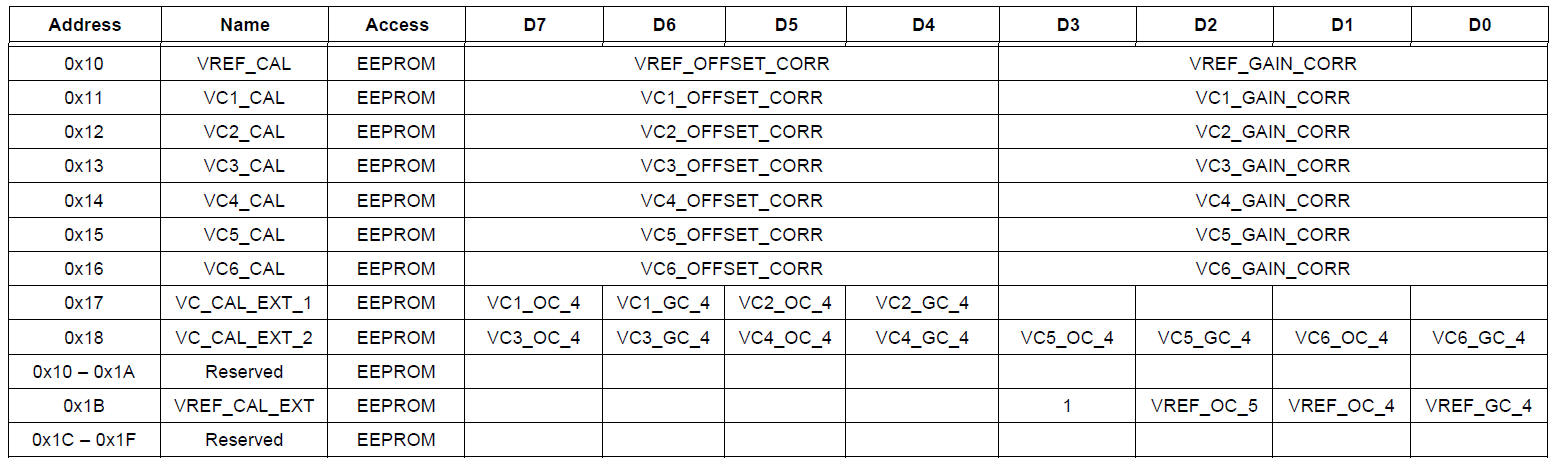
As far as I understand from the data-sheet the values are 5-bit 2's compliment number, except VREF OC which is 6-bit, which we'll ignore. To be negative, the high bit needs to be set just like an 8/16-bit 2's compliment . When looking at the software I see some positive and some negative values.
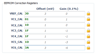
Offset(mV) Gain(0.1%)
VREF_CAL 3 0
VC1_CAL 0 1
VC2_CAL 1 0
VC3_CAL 1 -1
VC4_CAL 1 -1
VC5_CAL 1 -3
VC6_CAL 3 -6

The issue is when I read the EEPROM out the the I2C either myself or looking at the communications I don't every see the high bit being set. Looking at the comms log I see

I2C_R: 30 30 70
I2C_R: 31 01 CD
I2C_R: 32 10 C4
I2C_R: 33 1F C3
I2C_R: 34 1F 15
I2C_R: 35 1D 31
I2C_R: 36 3A BA
I2C_R: 37 04 2A
I2C_R: 38 00 B7
I2C_R: 3B 00 C9
Left number is the chip address + register (so 0x30 is is register 0x10). Middle number is the value, right number is CRC. Putting a scope on the I2C and the values I see on the scope match the software.
So all of the bits at address 0x18 (VC_CAL_EXT_2) and 0x1B (VREF_CAL_EXT) are 0, so I shouldn't be seeing any negative numbers on VC3/VC4/VC5/VC6. Also the datasheet says 0x1B bit 3 should always be 1, and it's obviously not.
Can anybody explain what's going on here? Is this a software bug and these should be positive values? VC3_GC and VC4_GC as +1.5% gain instead of -0.1%?
  • Just to clarify...If its a 5-bit two's complement, wouldn't a data value of 0x1F = -1? Wouldn't 0x1D = -3 ? Seems like the high bit is being set.

  • The registers are split into two parts, the upper 4 bits are bits 0-3 of the offset correction, the lower 4 bits are bits 0-3 of the gain correction. Bit 4 (the high bit) is in register 0x17 and 0x18 which are all 0

  • One possibility is that the software is ignoring the high value bit registers (even though it's reading them) and treating the numbers's as 4-bit 2's compiment instead of 5-bit. This seems to match with the values it's displaying.

    This is what's being shown in the software. 0xF is a 4-bit 2's compiment -1, 0xD is 4-bit 2's compliment -3. Even though  VC_CAL_EXT_1/2 registers are actually required to get these numbers it doesn't show them anywhere, and it's acting like they aren't present.

    Looking at both the EVM and hardware documentation I'm almost certain there is a disconnect between the two.

    The EVM/software documentation says 

    "Each gain value is derived from the top four bits (nibble) of the register value. This number is a signed 2’s complement representation in the range of –8 to +7. The units are in mV."

    The BQ76925 Datasheet says

    "The cell voltage offset and gain correction factors are stored as 5-bit signed integers in 2’s complement format. The most significant bits (VCn_OC_4, VCn_GC_4) are stored separately and must be concatenated with the least significant bits (VCn_OFFSET_CORR, VCn_GAIN_CORR)."

    I'd just suspect that software of being wrong and the datasheet correct, but if I'm reading the values right, I think I actually get a more accurate result using the software's 4-bit signed integers.

    Should I raise a support ticket for this? There's definitely a documentation disconnect here, and I'm not sure what to trust?

  • Anybody? I can't be the first person to use the evaluation software and notice these problems.

  • +1


    Actually it looks like reading register 0x1B (Vref_Cal_ext) is 0x00 when it should be 0x08. My customer also get correct value for reading Vref_Cal alone as 4bit 2-complement.


    Can we get official confirmation of this? and having the EVM and SW documentation to match?

    Olivier

  • The original EVMs were built with pre-production parts which used 4 bit gain and offset correction.  The evaluation sofware recognizes the device version which is displayed in the bottom border of the GUI window.  The pre-production parts will show Chip ID v1.1.

    The datasheet is correct for production parts which use the 5 or 6 bit correction factors. If you mount a new device to the EVM board, or interface the adapter to a board with a new device, the software will recognize the part as v1.2 and use the datasheet format correction.

    For either part version the software will show the correct decimal value, but the EVMs with version 1.1 devices will not be good references to follow the datasheet calculation methods from the register values as shown above in this thread.