This thread has been locked.

If you have a related question, please click the "Ask a related question" button in the top right corner. The newly created question will be automatically linked to this question.

LM5118 boost issue

Other Parts Discussed in Thread: LM5118

Hi all,

I designed a buck-boost converter using the LM5118, pretty similar to the datasheet example design. 

Input: 6-70V 

Output: 12V 3A

Buck mode is working, I've tried till 35V input and a 2A load, works fine. Under ~14V input it stops working, at the output it gives around input -  ~1-2V (probably the diodes drop) . it will still supply me with the right current tough.

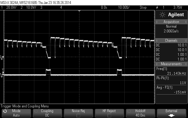
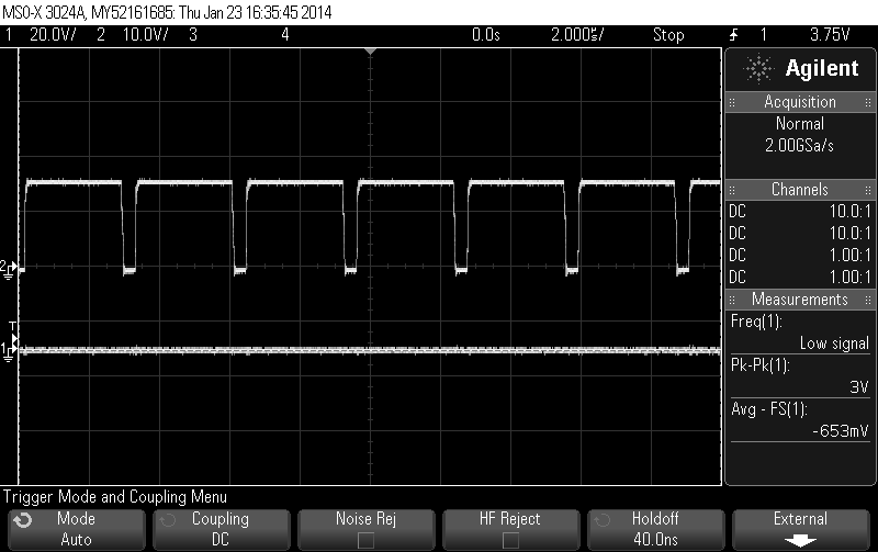
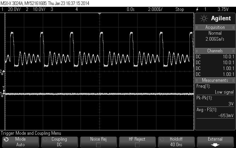
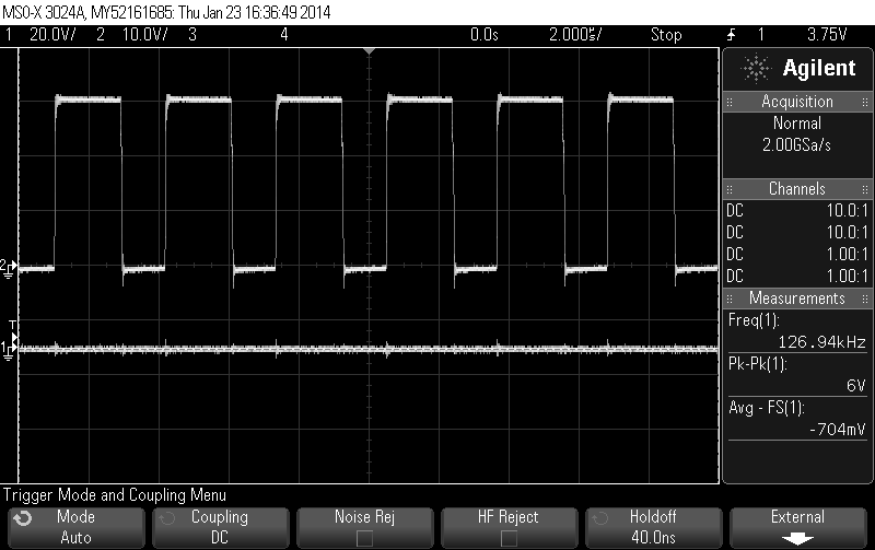
The voltage would not boost, at the gate of the low-side mosfet is nothing happening with load, without load there is a signal.

At the gate of the High-side mosfet there are peak voltages far ABOVE input (yeah, the gate is actually boosting for some reason, so the gate voltage is actually higher than the source voltage). On both source and gate there is a sinus-form signal before the square wave.

I really have no clue what is the problem, since the buck is working great.

Any help would be appreciated, regards Bas

  • Hi

    Are you following EVM component selections ? Can you show some waveforms and schematic ?

    Regards,

  • Hi,

    I'm not known with EVM, so I'm afraid I can't answer that one.

    My schematic is:

    Mosfets: 

    INTERNATIONAL RECTIFIER - IRLH5030TRPBF - MOSFET,N CH,100V,100A,PQFN56

    Diodes:

    D1: VISHAY FORMERLY I.R. - VS-12CWQ10FNPBF. - DIODE, RECTIFIER, 6AX2, D-PAK

    D2: ON SEMICONDUCTOR - MBRD1035CTLT4G - DIODE, SCHOTTKY, 10A, 35V, TO-252-3

    For now I'm unable to post the waveforms. 

  • These are the waveforms of the mosfet gates, the upper one is the High-side gate, the lower one is the low-side gate:

    input 8V, no load (output around 8)

    input 8V, 1A load (output around 6)

    input 20V, no load (output 12)

    input 20V, 1A load (output 12)

  • Hi

    You shcematic is almost same as EVM design, except VCCX supply and current sense filter I cannot see any issue.

    Please refer http://www.ti.com/tool/lm5118eval and try R-C filter at CS pin. Also disconnect VCCX from Vout

    Regards

  • To be sure, we are talking here about a PCB, not a breadboard I can push and pull at everything I like.

    I will try to remove the connection between  VCCX and the output.  The current sense filter is not applied in that EVM design ass well? the 0Ohm resister isn't doing a lot and the capacitor is a "NA".

    But tell me if I'm wrong but how could the filter be the problem by a fine working buck? (making great use of CS as well). As showed on the Waveforms the High-side gate driver is working great but the low-side gate driver is just not working. I will try, but is there anything else that  "decides" how the low-side gate driver is functioning? 

  • Hi

    I am not saying you are wrong. Your schematic looks nice to me as you believe, but the converter has an issue right now as we know.

    EVM schematic is the same as your schematic except some small differences and it works fine. That why I'd like to start from making two schematics same.

    If still there is a problem on your board while the scematics are the same each other, I guess this means there might be a wrong component populated or layout quality is not good enough.

    Have you ever replaced the low side MOSFET and LM5118 ? Your circuit should work well based on the schematic.

    Regards,


  • Yeah, I will try that. 

    I'm soldering a second board to check if the problem are any defect components. The low-side mosfet can't be the problem since it is the gate of the Mosfet that is never high. The chip is not sending a signal to the gate while this is just 1 track, pin to gate, nothing else.

    So the biggest question is: Why is the chip not sending a signal to the low-side mosfet? 

  • The duplicate of the board is working perfect, I guess the problem was a defect chip.