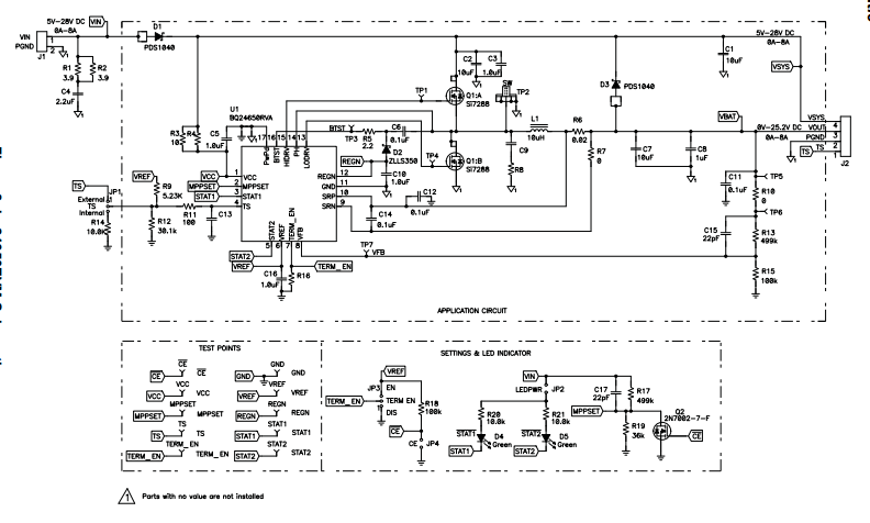
We have the BQ24650EVM and are testing the chip charging a 3.3V nominal (3.65V charge) 3300mAH LiFePO4 battery from various voltage sources.
We altered the evaluation board as follows:
R13: 499K -> 78.7K
R15: 100K -> 115K
R19: 30K fixed + 100K POT
Changing R14 and R15 resulted in a 3.65V charge voltage which is what we needed. The R19 alteration allows us to change between a 12V solar panel MPPT of ~17.8V and a 6V solar panel MPPT of ~5.8V.
We began testing with the board powered from a 12V solar panel (R19 adjusted for 36K) and all seemed to be working well. However, when we brought the device inside and attempted to use a 12V battery as the power supply we received no charge. Realizing this was likely due to the fact that the voltage was below 17.8V (The MPPT threshold) the POT was adjusted to the 5.8V MPPT level. The circuit then operated as expected.
My question revolves around if there is a way to configure for both DC inputs between 5-16V as well as a 12V solar panel? We were thinking that we could just set the MPPT level to below 5V, but were not sure how this would then affect the solar charging efficiency/functionality. Our other thought was possibly using a programmable resistor so that we can change the MPPSET level based on a detected voltage. (Note that we will have two separate lines coming into a power path switch and decide which one to use for charging, so we would know if it was a DC source or a solar input. Our issue here is what happens if the programmable resistor is not powered when we try to charge the battery [this could happen if the battery is dead])
Any suggestions regarding how best to deal with these input requirements?