Hello,
I'm using the TPS61202 to step up a LiPo battery to 5V, with resistors thrown in so the UVLO will trigger at 2.7V. The circuit worked reliably the first couple of power cycles, but now it does not work immediately on startup. I tried probing the UVLO pin to check what voltage was arriving, and that action apparently caused the component to start working again. Further experimentation showed that tapping the junction with an unconnected conductor, or even my finger, was enough to cause the component to start delivering the expected 5V.
Looking on the board, I saw the recommendation that I use the TPS6107x family extended soft-start application note (linked again here) to limit inrush current. I don't need a particularly fast startup time for this; I used a 10uF cap and a 1K resistor, which I know is outside the table provided in the notes. This did not address the problem, but it's possible that my choice of values here is to blame for that.
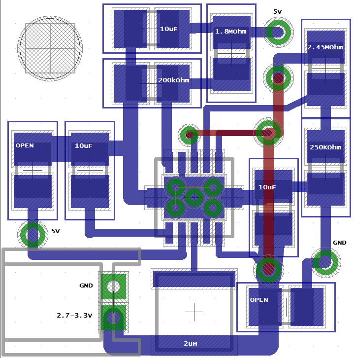
I've done what I can to rule out bad solder joints. I suspected that I had some physical problem with the board - a component lifting from the board that by pushing with the probe was coming back into contact - but it seems that is not the case, since I cannot "start" it by probing it with a nonconductor, but I can by probing with a conductor. My other thought now is that I have some unintentional fuzziness in my ground, and my probing is siphoning static charge or something. Accordingly, I've attached a schematic showing the conductor on the PCB. The soft-startup components are not shown.
Is there some fault in my grounding that jumps out at you? Maybe there's an aberrant capacitor value in here, although I've checked the datasheet several times looking for that now.
Thank you for your help.