This thread has been locked.

If you have a related question, please click the "Ask a related question" button in the top right corner. The newly created question will be automatically linked to this question.

LM5025 variable frequency and duty-cycle

Other Parts Discussed in Thread: LM5025

Hello,

is it possible to control the frequency (150kHz-500kHz) and the duty-cycle (0-80%) of the LM5025? Can I use the SYNC-Pin for this? When I use the SYNC-Pin in PSpice the outputs are low (0V).

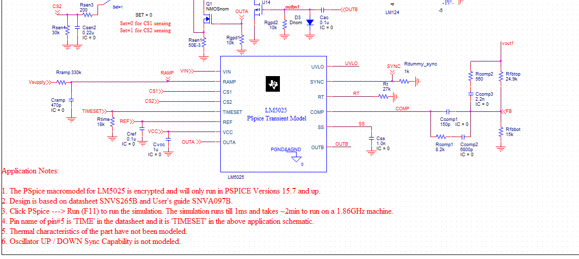
My circuit with synchronization:

Thanks

Tobias

  • Pin9 - An external resistor connected from this pin to GND sets the
    oscillator frequency. This pin can also accept an AC-coupled
    input for synchronization from an external clock.
    Oscillator frequency range up to 2 MHz. (TI data sheet holds some of those answers)
     
    Duty cycle is relative to current sink into load and typical limiting resistor not usually good idea to force that aspect on demand without knowing the loads current profile in advance.
     
    Only my opinion, difficult that request to do on a variable demand such as a motor PWM is capable of.
  • ok thanks.

    I would like to drive a half bridge with the controller LM5025. The controller I'd like to be controlled with a PWM from a microcontroller. I dont know if this is possible.

    Thanks a lot!

    Tobias

  • The advantage of using a PWM to drive a 1/2 bridge is the unique ability of controllable up down counters that modify the duty cycle with software monitoring an internal ADC of the external current loop. The counters trigger internal comparators creating a center aligned bipolar output wave form using a high and low side MOSFET switch driver controlled by embedded software. The output wave form can be edge aligned on left or right if need be.

    BTW: PWM code loaded to controller flash memory can be modified using TI's Code Composer Studio 5.4 also to help  learn the C++ language, compile code to binary prior to flashing the chip and do other useful things.

  • TI makes several evaluation boards to experiment with DSP using PWM, stretching here you are attempting to make a variable voltage, current regulated power supply? Maybe these evaluation kits will stimulate the idea engines.

    http://www.digikey.com/product-search/en/programmers-development-systems/evaluation-boards-dc-dc-ac-dc-off-line-smps/2622539?k=Piccolo

    Digikey was selling a standalone Piccolo DSP controller evaluation board for $17.00 last month but could not locate in searches. That Piccolo DSP controller had two PWM channels as I recall, could be used to control passive components in such to regulate voltage, current and provide duty cycle management using examples of prewritten code you can modify using CC5.

     One can configure a digital entry panel GUI made using CC5 studio GUI composer which could use the USB port to program the power supply outputs for the exact duty cycle desired and update the user in near real time the actual  voltage and current when supply is under a load.

  • The controller I'd like to be controlled with a PWM from a microcontroller. I dont know if this is possible.

    Would certainly believe that to be possible given the huge impact DSP has made upon PWM last few years.

    I need a GUI controlled power supply right now!!! :)

    This link takes one to WEBench tool matching PWR topology to ones power requirements by clicking on any blue titles several bottom of page. 

    http://www.ti.com/ww/en/analog/power_management/isolated-power.html

  • Tobias; TI has apparently been where you want to go with LM5025 maybe found that was not a practical approach to power solution. Guessing much as somewhat vague to do finally A & B Spice outputs first missed by me.

    Spending time effort to steer you in the right direction was not rewarded by a nice green answered check mark or even yellow suggest answers. Only silence and new posting of another trouble asking for help. This poster has left the Power forum. :( 

  • Hi Tobias,

    The SYNC PIN functionality has not been modeled in PSpice model you are using. It is mentioned in the application notes section of the PSpice model under 6 as shown in the below image.

    Thanks and regards,

    Irappa