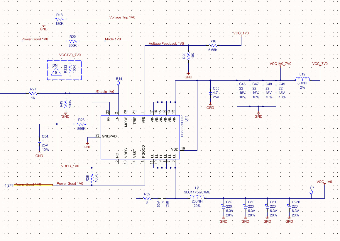
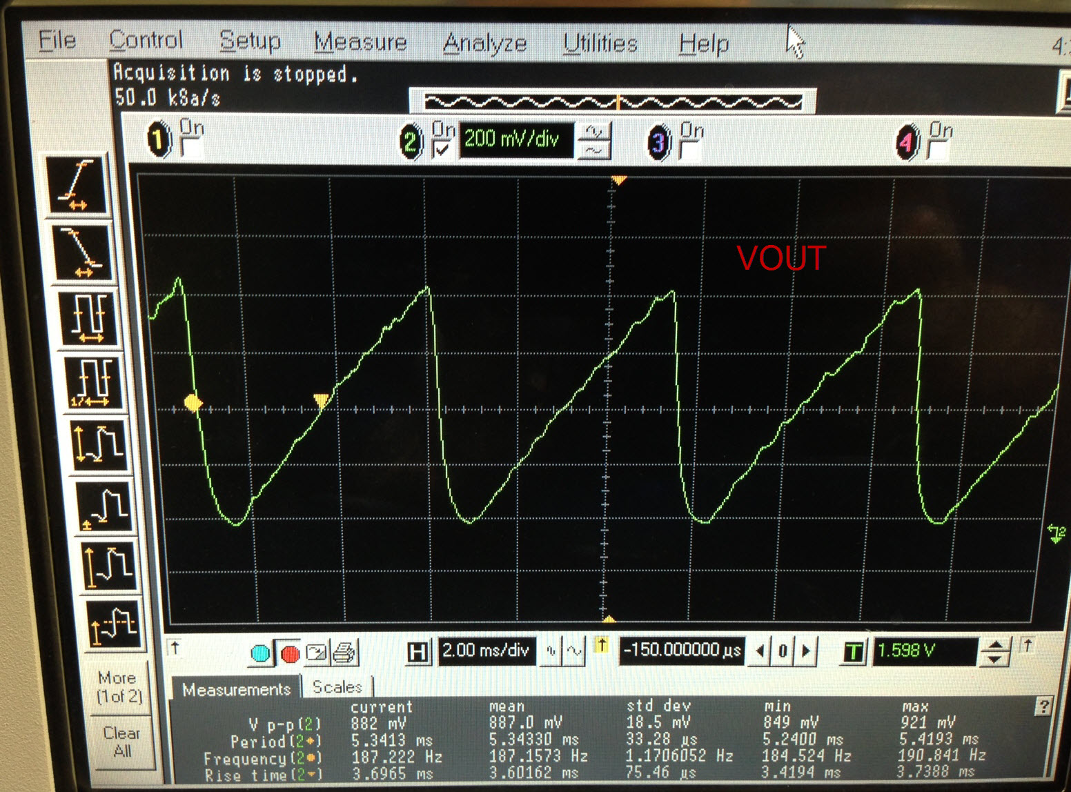
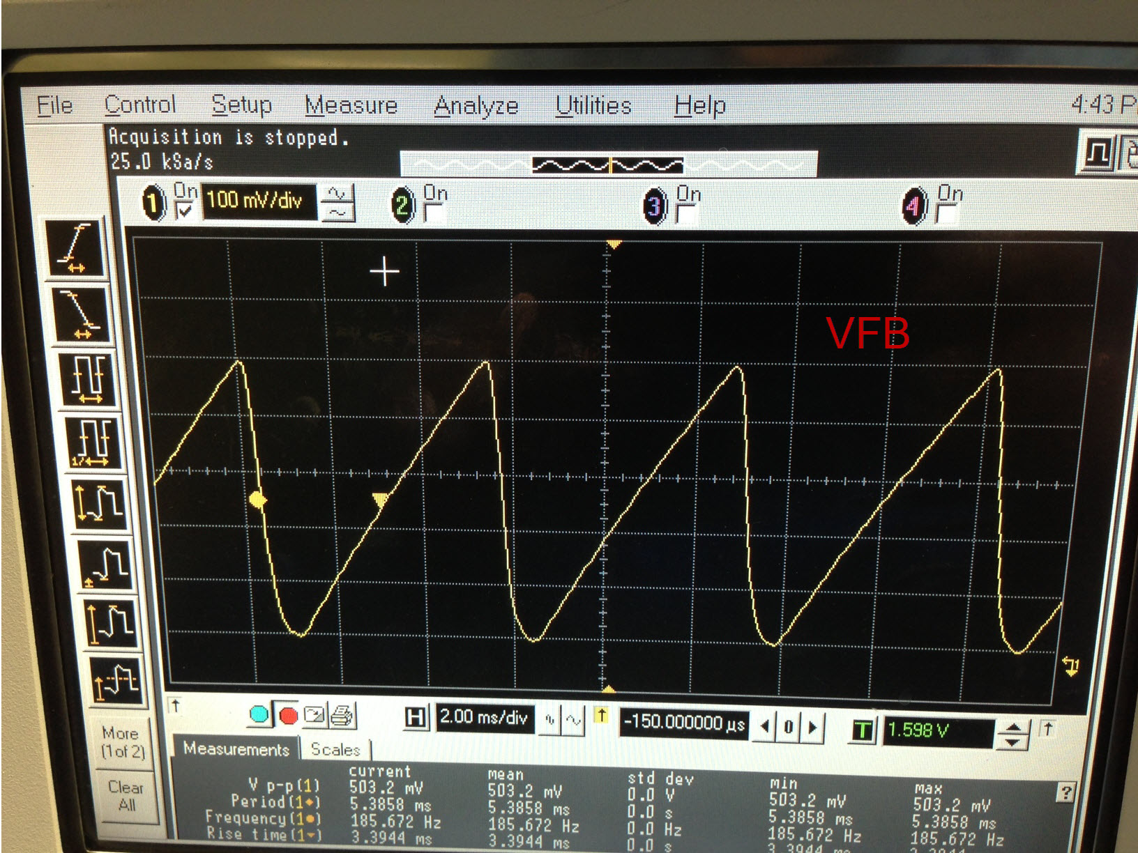
I implemented the TPS53355 in a circuit where it provides the core voltage of 1.0V to four FPGAs. The peak current is approximately 25A. We noticed when the fourth FPGA is programmed, the regulator voltage drops 500mV and all FPGAs turn off, then the voltage rises back up to 1V. Sometimes we are able to have all 4 FPGAs running for a few minutes before this happens (which is most likely due to the load current increasing as the temperature in the FPGAs rises). I implemented a ~21A static load using power resistors connected to another board only populated with the supply, output capacitors, and capacitors which normally decouple the FPGA. When I power on the regulator the output immediately begins to show a sawtooth wave in which the voltage tries to ramp up to 1V but only achieves ~880mV before dropping to zero. When I add resistance to the circuit and change the load to ~17A the voltage regulates properly at 1V. Even though the current limiting resistor is set to ~29A, I removed it entirely to rule out an overcurrent issue. I also removed the resistor for soft start thinking the output was rising too slowly due to the amount of capacitance on the load and tripping the UVP. I am hesitant to believe it is a loop stability issue because the value of the capacitance and ESR in the load does not change, only the output current. The regulator was not designed with a loop compensation network as it follows the specialty polymer capacitors (SP-CAP) design in the datasheet. However, at the site of the FPGAs there are (8) 330uF tantalums, (12) 100uF ceramics, and (20) 4.7uF ceramic decoupling capacitors on this rail. Thinking the 100uF low ESR ceramic capacitors could be inducing stability problems I removed all 12 of them, but this did not solve the issue. At sub-20A loads when the regulator is regulating properly the 0.6V feedback point looks relatively clean. Furthermore, the input voltage remains a clean 7V and the EN voltage is 5V. I am attaching images of the layout, schematic, as well as scope plots of VOUT and VFB. The VFB trace is stripline and is surrounded by Ground on all sides.