Hi everyone thanks for help,
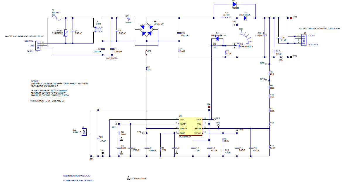
Schematic of a boost up regulator without a secondary AC isolation transformer diverts rectifies any would be load side AC current (Ripple) entering B+ using D2 across inductor also stopping reverse current flow.
That diode (D2) by itself without an inductor or switcher IC does not stop the full wave bridge DC ground from floating 69 VAC above earth ground. More over when attempting to test for any current flow between earth ground & DC ground, just touching the DVM probe (10 amp scale) immediately blows fuse on the AC side tripping 20 amp circuit breaker in electrical panel. This is an extremely dangerous configuration should the two grounds come together.
The wave bridge DC is filtered using two 1200uf 250V in parallel coupled to two more 200uf in parallel 27k bleed off load. That circuit produces +170 VDC and +150 VDC 1.5amp load .3mv ripple with no switcher components inline. BTW: An extremely fast switching silicon carbide diode D3 boosts C16 voltage up to +390 VDC.
3386.Diode Silicon Carbide 600Volt C3D04060A.pdf
Does the IC switcher & inductor shown in schematic provide AC ground DC ground isolation or has no one ever cared to know just how extremely dangerous a non-isolated floating DC ground is.
Especially becomes a safety issue if another AC offline DC source provides VCC to the circuit being powered using the higher voltage DC supply such as for a motor controller bridge DC rail source separated by a 3.3vdc MCU power adapter. High voltage high current DC ground meets low voltage low current DC ground both needing a common sink. Webench can not find this configuration guessing because it hasn't been invented. Needing +150VDC 6.5amps (+15vdc, +3.3vdc 500ma average) in the same offline switcher topology. Then ground isolation becomes somewhat a mute point though the safety issue would still remain.
The only difference between this circuit below and the one described above is the bridge shown below is not being DC filtered using electrolytic caps prior to boosting the voltage at C16. Hard to believe that alone could make DC ground rise above AC ground +69VAC potential.