This thread has been locked.

If you have a related question, please click the "Ask a related question" button in the top right corner. The newly created question will be automatically linked to this question.

LM5002 Disable Control

Other Parts Discussed in Thread: LM5002

Hi:

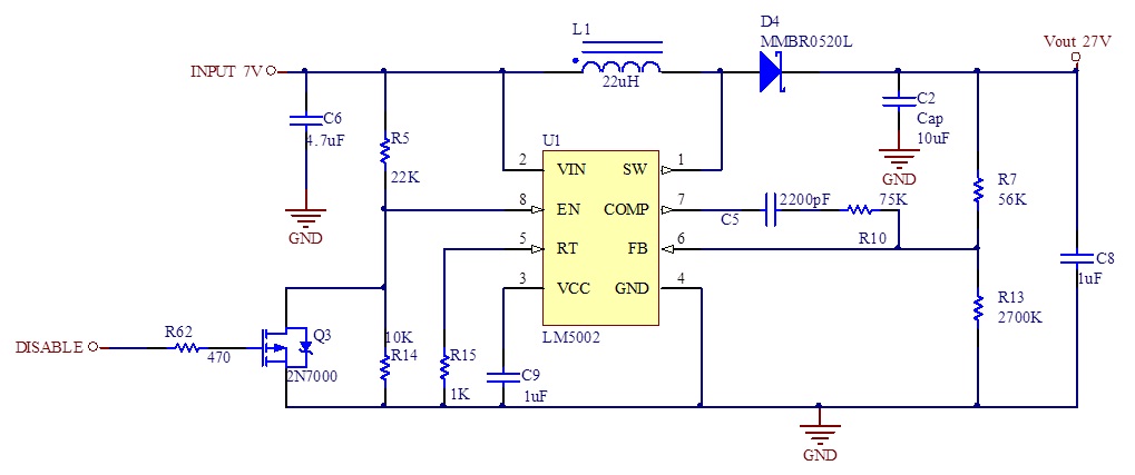
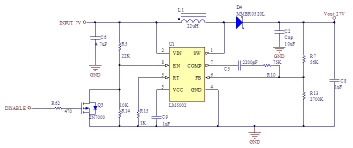
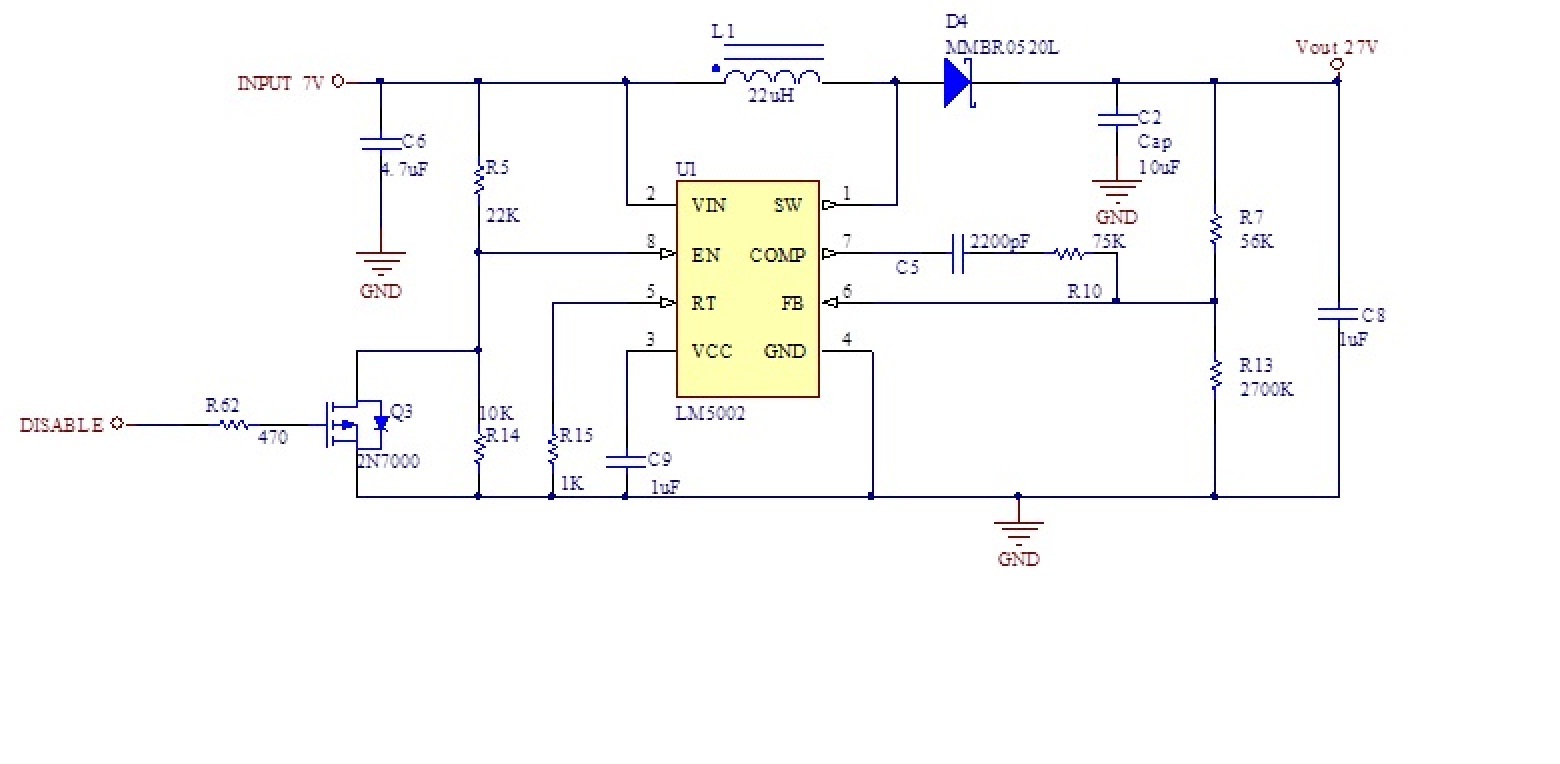
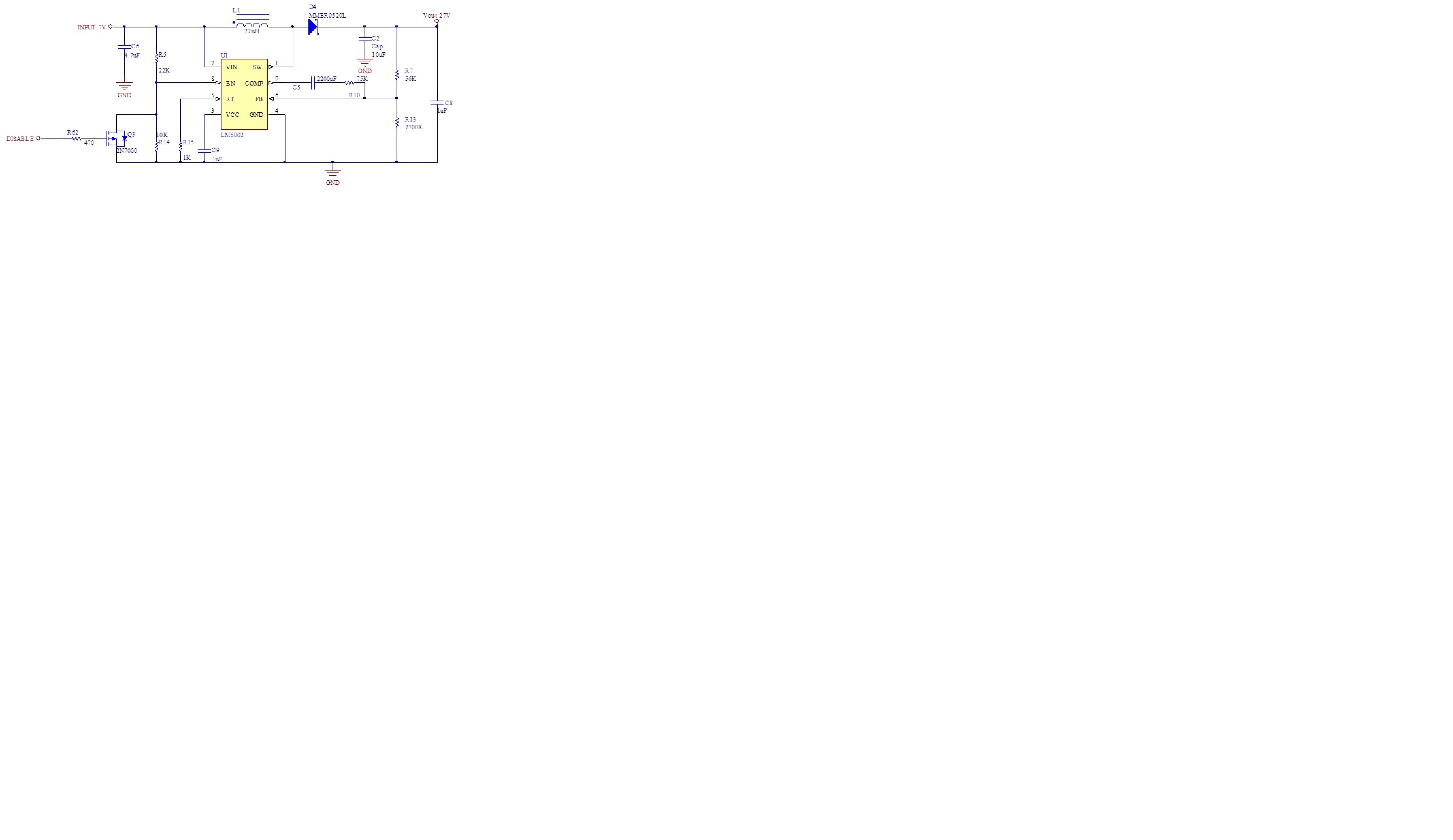
 Im using the LM5002 as a boost converter, it works fine, but when I try the disable control, explained in the datasheet page 12 figure 19, it doesn't work (I'm not using standby option). My components are R1= 470, R2=10K and transistor 2N7000. If I switch the system supply with the transistor gate at high level, it holds the converter off, when the transistor gate goes low the converter start working. The problem is when I try to switch off the IC, if the converter is working, it ignore the control signal at transistor gate. I have also tried to jump the resistor R2 with a wire (EN pin connected to GND) during normal working and nothing happens. What am I doing wrong?

Regards

Fernando

http://www.ti.com/lit/ds/symlink/lm5002.pdf

  • From the description it is hard to figure out what is wrong.  Would you please provide your own schematic?  By the way, what is your input voltage, and what is the gate voltage for 2N7000 when you try to disable the LM5002?  Though feasible, R1=470 looks too small with respect to R2=10k.  

    Thanks,

    Youhao Xi,  System and Applications Engineering,  TI SVA PPD-NPS

  • Hi:

      The resistors are calculated for enable the converter when the input power reach 4V with an "I divider" value of 120uA (page 12 figure 18). To disable the converter the gate is at 5V and to enable it, is at 0V. Here is the schemmatic:


    Thanks in advance.

  • Still a little confusing:  I am afraid something is not described accurately.  You showed Q3 a P-FET, but 2N7000 is actually an N-FET.  Can you confirm that Q3 is indeed an N-FET? Your previous post said R1=470 when referring to TI datasheet. And it turns out "R1" is 22k, and the 470 Ohm is at the gate of your Q3.  I am willing to help, but in order for us to help you better, please be accurate in reporting the problem. 

    By the way, when you short your R14 with a jumper wire, the LM5002 must stop switching.  If you see switching not stopped, the LM5002 was either damaged somehow, or your circuit board has error.  

    Thanks,

    Youhao Xi, System and Applications Engineering, TI SVA PPD-NPS


  • You are right, I wasn't very clear, I apologize, too many hours in front of the computer, sorry. The mosfet is an N-channel, of course and the resistor R1 is 22K. The EN/UVLO works correctly, I think, because the converter start to work when the supply volt reach 4v.

    I have changed the IC, and remove the mosfet. The behaviour is the same. If I jump the R14, and swtich ON the voltage supply, the converter doesn't work, when I remove the short it start working but, if I short with the converter working nothing happens. I have measure the voltage in the EN pin in that case and is very close to 0v but with a little bit of ripple.

    Thanks

    Fernando