This thread has been locked.
If you have a related question, please click the "Ask a related question" button in the top right corner. The newly created question will be automatically linked to this question.
Hi Ryuji,
I am curious as to why they are choosing to adjust the LED current like this? A similar function is achieved via the PWM input pin already on this device. I would recommend that they adjust their current through the duty cycle of the PWM rather than using a FET like they are doing now.
Thanks,
Nate
Hi Ryuji,
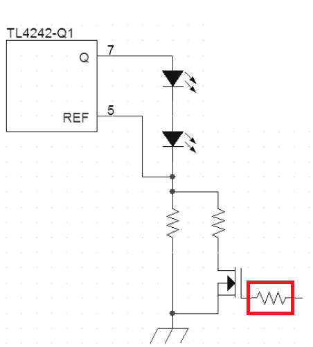
I think what would happen is the opposite of what you have suggested. There will probably be minimal voltage droop or overshoot due to the load change given it is in the ~1ohm range. Because this resistor is used for current sense instead of current limiting, the output current will start the change to match the new reference value. Since there is a finite delay from sensing the current to adjusting it, there could be some current droops or overshoot when changing Rref.
If overshoot/droop become a problem, a resistor can be added to the gate of the FET (shown below) to slow the transition time and better control the slew rate.
Let me know if you have any more questions.
Best Regards,
Adam Hoover
Drivers and Load Switch Applications Team