This thread has been locked.

If you have a related question, please click the "Ask a related question" button in the top right corner. The newly created question will be automatically linked to this question.

LM3150 - Webench Efficiency calculations vs. reality

Other Parts Discussed in Thread: LM3150

Hello,

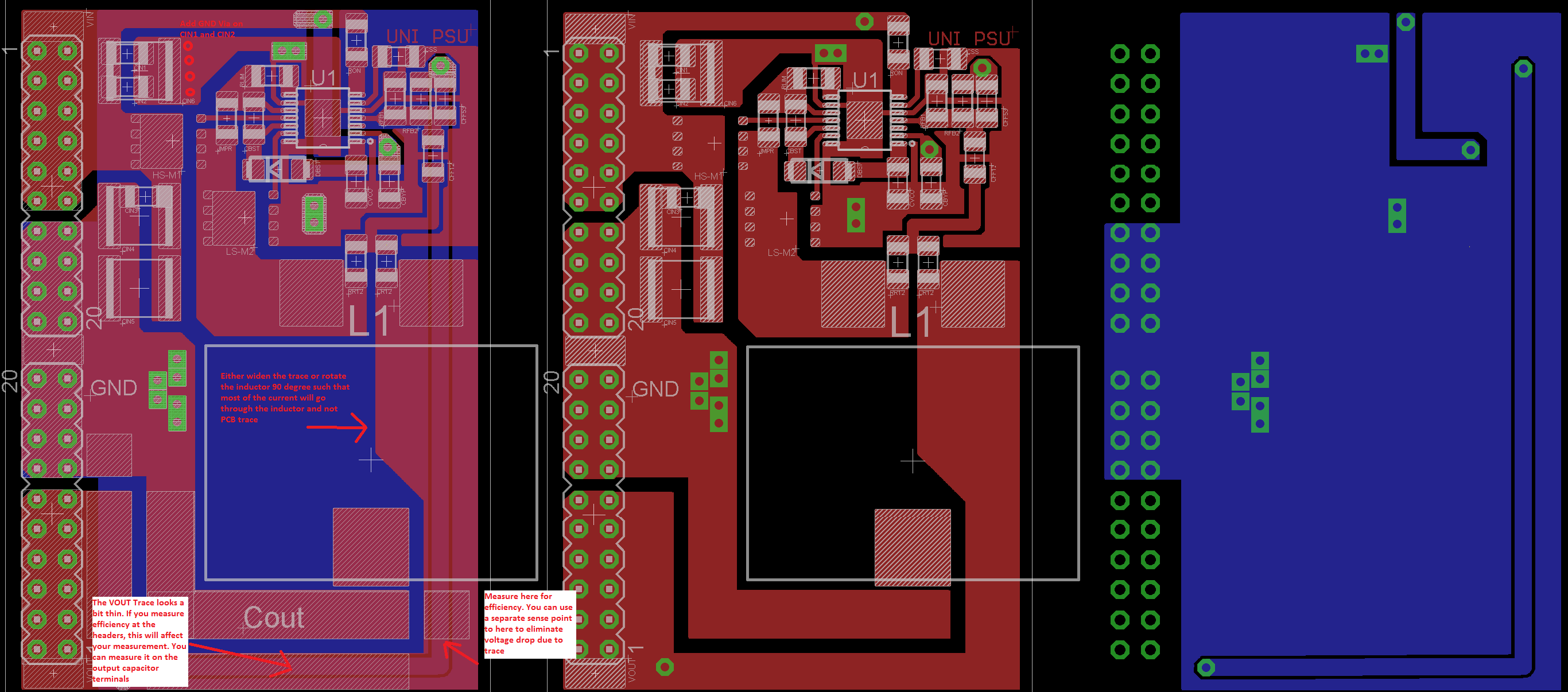
I would like to ask, if Webench calculations of efficiency are really reachable. Because wee have created universal PCB for 3.3V@5A, 5V@5A and 12V@8A(design attached). Currently we are testing a version of 5V and Webench calculated efficiency up to 97%(file attached), but we can´t get over 89% of efficiency. 

In last design we used 105um PCB, which increases average efficiency from 87% to 89%.

Latest measurements:

Vin 28V, Vout 5.00V, Iin 0.01A, Iout 0.00A
Vin 28V, Vout 4.99V, Iin 0.09A, Iout 0.44A - 87.1%
Vin 28V, Vout 5.01V, Iin 0.85A, Iout 4.15A - 87.4%

I don't think, that there is a mistake in selected parts.  So maybe we still have some troubles with PCB layout or the values given by Webench are unreal...

Could you please help us to find out what's wrong? Thank you


*Dbst, Cr12 and Rr12 not used in 5V

Webench data: 2045.lm3150-5v.pdf

  • Hi,

    Can you describe how you measure the efficiency? It seems that you have 3 output voltages in here. 

    When you measure efficiency for one of the output, are the other outputs disabled? 

    Thanks

    -Arief

  • Hi Zybeek,

    The efficiency of the part depends on the passive components such as DCR of the inductor and the ESR of electrolytic capacitors. Another point to consider is the width of traces such as Switch pin and Vin traces. Please keep your diode and inductor as close as possible to reduce the SW loop path. The selection of diode will also greatly affect efficiency in non-synchronous part designs.

    Thanks,

    Anston

  • Hi,

    The three voltages are measurements of the ones output reaction to connected load. We measure idle voltage for comparison then two measurements with two different loads connected.

    Thank you for your advice with SW loop. We tried to stick the FETs as close as possible to each other but we thought the coil could be a bit in distance. Could you please share an example of diode which would be suitable by your opinion?

    Also We'd like to ask if it's a good idea to place the diode with cboost on bottom layer. It could lower the FET gate noise, couldnt it?

    Thank you very much for your answers

  • Hi Krystof, 

    After comparing your operating condition with the EVM, it seems that the efficiency that you have given (87%) with VIN of 28V and 5V output is in the ball park of what they actually have in the EVM. Here is the link for the EVM
    http://www.ti.com/lit/ug/snva371d/snva371d.pdf

    I have been looking at the efficiency curve in the document and found nothing that shows when VIN is greater than 24V and efficiency higher than 90%

    I will try to contact our webench team to see if there is an error here. 
    Another thing that you could verify is that if the MOSFET are driven with the appropriate voltage at the gate.  If the gate drive signal is too low, the MOSFET Rds on will be high and that could impact your efficiency

    Thanks

    -Arief

  • Hi Krystof,

    Here is what our webench team response on your inquiry. In regards of efficiency:

    " The difference is quite large, but I checked the component power losses calculations, and I did not see anything out of place.  The power loss contributions come from the FETs, IC, inductor and the input and output capacitors.  The FETs being selected are TI NextFETs and have very small Qg values, but it aligns with the datasheet. 


    WEBENCH doesn’t account for any losses from the PCB layout, so that may account for some of the difference.  The customer is using 105um copper, which is about 1oz copper."


    Thanks and hopefully that helps

    -Arief

  • Hi, 

    thank you for verifying that. Only thing I would like to mention is that we are using NexFETs and the 105um PCB is actually 4oz. 

    We now know that we have efficiency which is comparable to eval board and could be considered stable, right? 
    Is there some improvement in the PCB we could do if we wanted to make it a bit more efficient?

    Thank you very much

  • Hi Krystof,

    Yes, i think the efficiency should be stable. Plus you already have a 4oz copper which is more than enough i believe, But, please do make sure that on your switch node that the duty cycle does not jitter. 

    Here is my comments in regards to the layout for efficiency. 

    Thanks

    -Arief