Hello.
Sorry for my bad english, but i'm not native language.
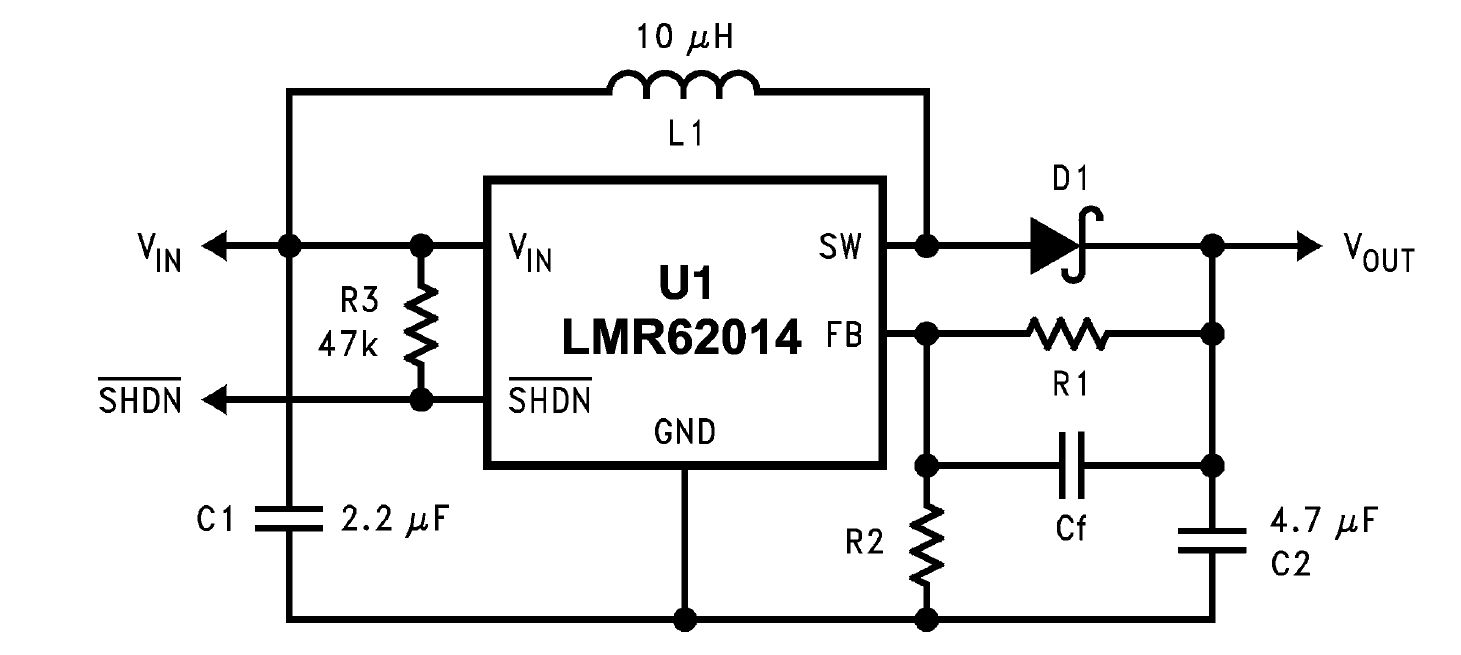
I try to realize boost converter with this product, particularly Vin=5V and Vout=12V, but it isn't work correctly. I realize circuit show at page 11 of LMR62014 datasheet. C1 and C2 are tantalum capacitor (2.2uF and 4.7uF respectively), D1 is a shottky diode, L1 is 10uH inductance Isat>4A, R3=47k, R1=100k, R2=12k and Cf=270pF disk ceramic capacitor. All components (except LMR62014) are a through hole components, because i realize this test circuit on bread-board.
Vout mean is about 12V, but ripple is very high, about 1,5Vpp. I try to insert 47uF tantalum capacitor at Vout pin and entity of ripple was little decrease (and period was increase). I did another test adding electrolict capacitor with 470uF capacitance value, but entity of ripple little decrease (1Vpp) and period was increase (frequency of ripple, in this case, was about 7Hz. With oscilloscope i measure Vin and i see DC component with low noise. When i connect DCDC converter, the 5V voltage present a square wave add with DC component.
In all test, Rload=390ohm, so Iout=31mA.
Where am i wrong? Can you help me?! Thank you. Gabriele.