This thread has been locked.

If you have a related question, please click the "Ask a related question" button in the top right corner. The newly created question will be automatically linked to this question.

LM2673 under performance

Other Parts Discussed in Thread: LM2673

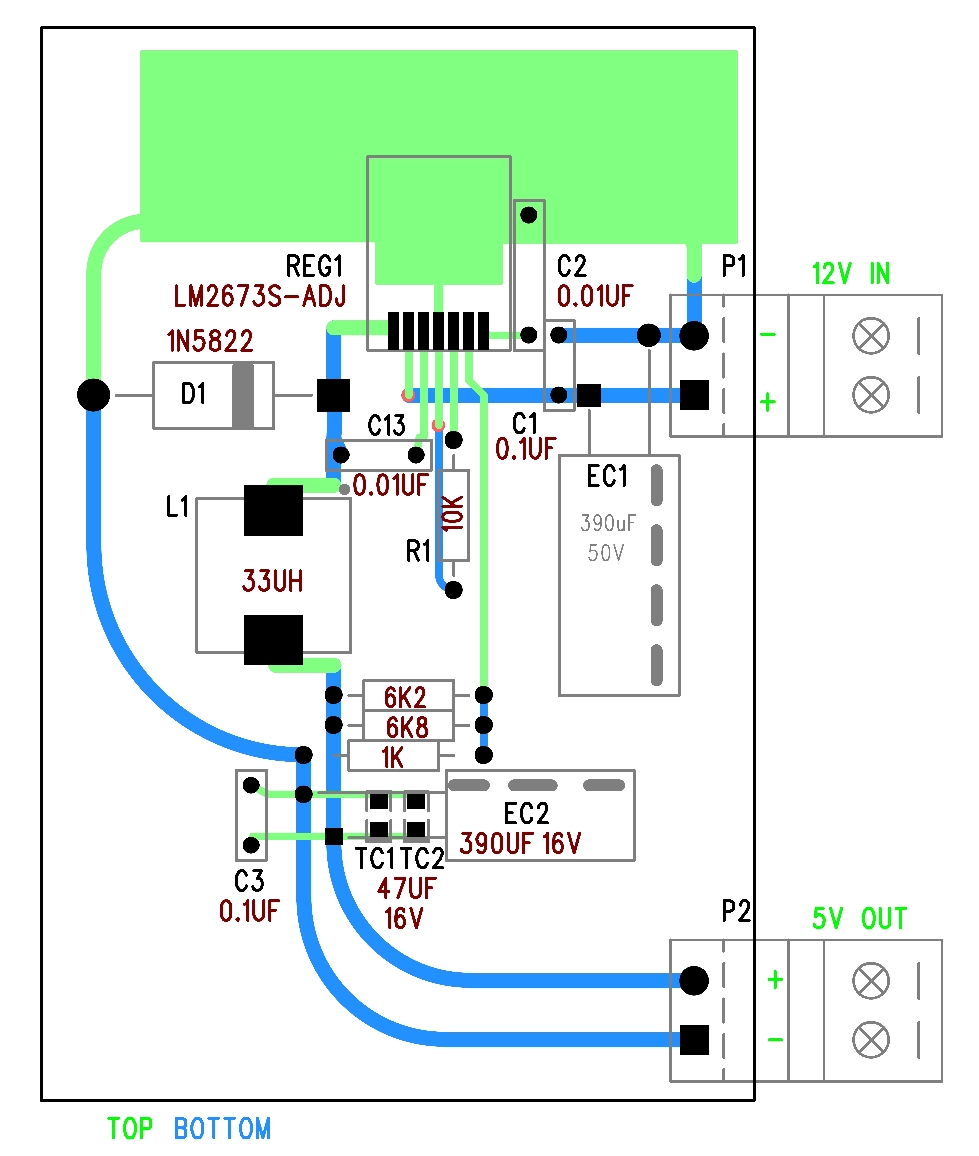
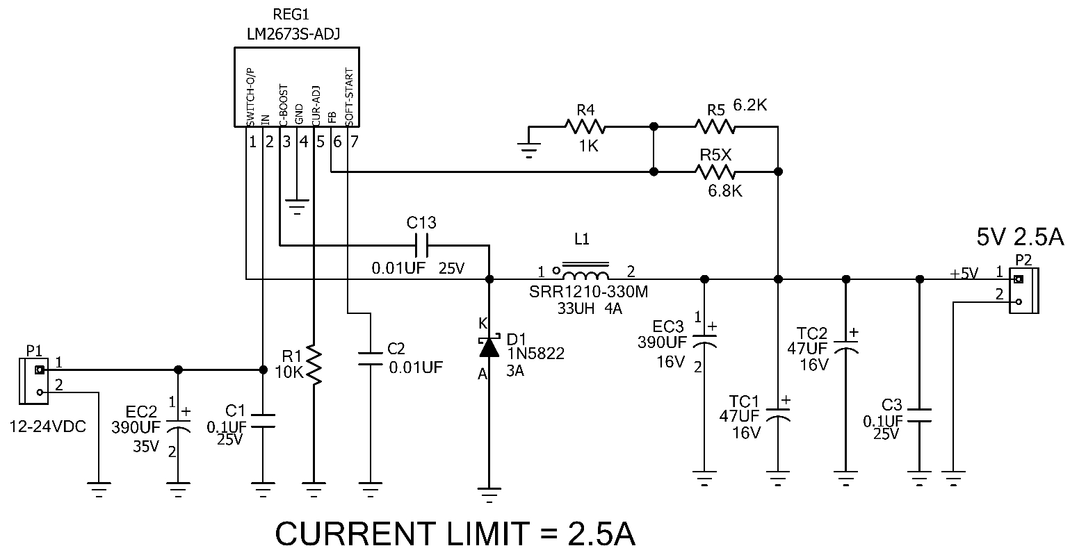
Via Webench, I got a design proposal with LM2673-adj to output 5V/2.5A from a supply ranged 10~26V.  Webench suggested soft-start and Boost capacitor as 0.01uF, current limit resistor=9.79K, power inductor=33uH

I builded the circuit on a bread board and tested.  The circuit was not performed as expected.  It was 5.2V at no load.  3.5V at 5.6ohm load.  Then the power inductor was changed from suggested 33uH to 10uH and boost cap to 0.02uF.  Then 4.85V at 5.6ohm was achieved.  But further test with 2.2ohm load got 3.02V.   Decreased current limit resistor to 2.7K slightly increased the output to 3.3V at 2.2ohm load.

Please advice where should I look into to improve the circuit performance.  Thanks for attention.

  • Hi Ben,

    Please attach a schematic of your design and layout so we can better understand the problem. There doesn't seem to be anything wrong with your component selection, but a schematic would help us confirm this.

    Thanks,

    Anston

  • Hi Anston,


    Here is the schematic and PCB layout for your reference.

    Thanks

    Ben

  • Latest trial:

    1.  D1 = MBRS360;    2.  Inductor=10uH;    3.  Boost cap=0.02uF

    Output at 2R2 load was improved to 3.2V but still far from 5V as promised.

  • Hello Ben,

    The BOM that Webench suggested should be correct. The thing with switch mode power supplies is that you cannot bread board them with long wire leads. Since they are switching at high frequencies, any additional lead length will add parasitics in the switching current path and cause instabilities. You have to adhere to the layout guidelines in the datasheet for the correct performance (page 9 of the datasheet). If you want, you could obtain the EVM from the TI store and prototype your design on that board. I hope this information helps. For your convenience I have attached a presentation on EMI pitfalls and methods on mitigating EMI along with this message. 

    Regards,
    Akshay

    Switching Power Supply Design_ EMI.ppt
  • Thanks Akshay, I builded another trial with SMD and place components closer.  With adjusting the current limit, I can get 2R2 loading at 5.06V output.  But there is limitation that 5.08V was achieved only at cool start.  When load was disconnected, output raised to 5.22V and OK.  But re-connecting 2R2 load I got output dropped and bounced between 4.0V and 4.7V.  In application, load may be freely unplugged and plugged, how this can be resolved?

  • Hello Ben,

    Are you still using the same kind of layout with thin traces and just moved the components closer? If you are able to load the supply at cold and not able to do so at room, then your IC might be heating up and the RdsON of the FET must be increasing. Can you measure the temperature of the IC at room when you can't load the part? I would suggest confirming that the DAP of the IC is indeed soldered down and if required increasing the heatsinking on the DAP of the IC.

    Regards,
    Akshay

  • Hi, Akshay,

    Besides moving closer, connection was done with 1mm wide solder track.    When output was bouncing at 2R2 load IC was not hot just warm,  Ground connected 20x40mm thick copper foil of 20x40mm was under IC.  Interesting is output stable at 3.5V under 2R load. 

    I guess at 2R2 load, IC reaches current limit threshold and causes bouncing.  When load current is well over current limit, it is stable.  Is my understanding correct?

  • Hello Ben,

    If load current is well over the current limit, you should be in current limit and your Vout would fall. Your instability, I believe, is more related to noise in the system. If your power traces such as the SW node trace and input trace are 1mm then you still have a problem. You need planes of copper pour on those nodes.

    I noticed from your previous post that you reduced the inductance from a suggested value of 33uH to 10uH. Did you have an issue at 33uH? By reducing your inductance, you now have larger ripple current and this could cause other current limiting problems. 

    If you'd like, we can ship out an EVM for LM2673 to your address. For this we'd need your postal address and phone number.

    Regards,
    Akshay

  • Akshay,  thanks for the hints.  the SW 1mm track is less than 8mm in total.  I shall replace the track with a piece of cut copper to try again.

    I worked the 33uH before but output was 4.8V at 5R6 load.  Thus inductor value was reduced, under 2R2 load, 15uH gave 4.8V while 10uH gave 5.03V.

    An EVM for LM2673 will be appreciated very much.  Here below is my address:

    12AB, Block 1, Wah Fung Industrial Centre

    33-39, Kwai Fung Crescent

    Kwai Chung, N.T.

    Hong Kong

    Tel: 852-91732575

  • My challenge here is to find an EVM. I will let you know about it soon.

    Regards,
    Akshay

  • Hi, any update on the EVM issue?

  • We'll be sending it out today. I will provide you the confirmation as soon as I get it.

    Regards,
    Akshay

  • Ben,

    We need your company's name, address and phone number. Please provide us with your company information. We are waiting to ship the board out.

    Regards,
    Akshay