This thread has been locked.

If you have a related question, please click the "Ask a related question" button in the top right corner. The newly created question will be automatically linked to this question.

TPS22929 inrush current

Other Parts Discussed in Thread: TPS22929D

Hello I'm Hidetoshi Matsunami.

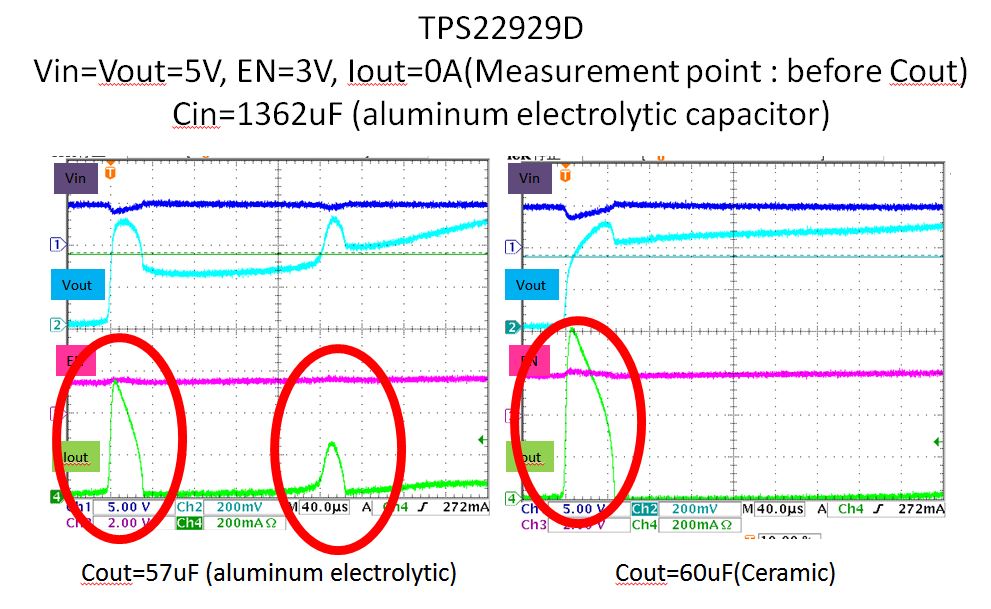
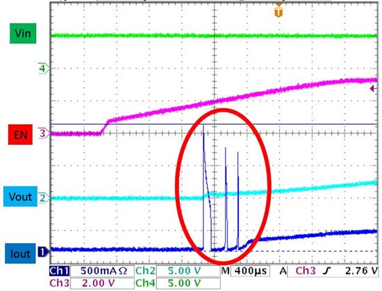
Could you tell me why did 3 times inrush current occur at the attached wave?

There is no description about Thermal Shutdown and Current Limit on the data sheet as far as I can see.

Therefore I don't know the reason.

Also Can the inrush current exceed the maximum continuous operating current of TPS22929?

Best Regards,

Hidetoshi Matsunami

  • I would like to know what the situation of this question is now.

    Best Regards,

    Hidetoshi Matsunami

  • Hi Hidetoshi Matsunami,

    What is the load on VOUT? What is being powered by this load switch?

    Also, which version of TPS22929 are you using? The different versions have different rise times.

    Regards,
    Stephen

  • Hi Stephan.


    Vout is connected to load along with 57uF Cout and EMI Filter(ACH32C-103 please see the below URL as ds).

    I will check the load to our customer

    http://roots.tdk.co.jp/rootsme.asp?ID=TJA099&NO=ACH32C-103-T001A&RT=1&DS=0

    I will send the circuit which I have to you if you can contact me directly.

    matsunami-h@clv.macnica.co.jp

    Also, our customer is using TPS22929D.


    Best Regards,

    Hidetoshi

  • The 57uF cap will cause some inrush current:
    Inrush = Cout * dV/dt = 57uF * 5V / (Rise Time)

    However, that will not yield the magnitude of current shown in the oscilloscope capture.
    The load circuit is drawing the heavy current.

    I do not believe that this device has a current limiting feature, but I will check and get back to you.

  • This device does not include current limit or over-temp shutdown features.

  • Hello Stephen,

    I appreciate your supports.

    I'll answer to customer.

    Best Regards,

    Hidetoshi Matsunami

  • Hello

    I would like to ask you some additional questions.

    Please find the attached PDF file.

    2538.TPS22929D inrush current for E2E.pdf

    1. Why are 2 inrush currents shown in the oscilloscope capture without Current Limit?

    2. What's the difference between Iout wave of measurement point A and B?

    Some data of the attached file seems like FET is off.

    Best Regards,

    Hidetoshi Matsunami

  • Hi Hidetoshi,


    Thanks for the additional info.  Starting with your second question, I'm guessing that measurement point A, is the red arrow labeld "1" on the first page of your attached document and measument point B is the blue arrow labeled 2.

    The difference in the Iout waveforms is that A is before the output capacitor and B is after.  So the current measured at B is just the current through the load while the current at A will be the current at B + the current flowing through the output capacitor. 

    This answers question 1 and explains why you see the spike at point A and not point B.  When the switch first turns on, the voltage differential between the input and output cause current to rush through the device and start charging the output cap.  Quickly thereafter, the circuitry that controls the output rise time senses the output capacitor is being charged too fast and kicks in.   Because the device does not provide current limiting, there will be some delay before the rise time circuit can react.


    Regards,

    Adam Hoover

    DLS Applications Team

  • Hi Adam,

    I appreciate your help.

    Please let me ask one more question.

    What's the difference between left waveform and right?

    Left waveform has 2 peak however left waveform has 1 peak.

    Is that dependent on output capacitor type? 

    Best Regards,

    Hidetoshi Matsunami

  • Hi Hidetoshi,

    The type of capacitor will have an effect as well as the difference in capacitances.  Is the output capacitor the only thing that is different between these two waveforms?  Has the position of the capacitor relative to the device changed at all? 


    Assuming yes, it appears the second peak is also being controlled by the rise time circuitry.  The rise time is an average measurement, which takes time.  The first spike occurs because it takes time to react to the current spike charging the output cap (as previously discussed).  But look at the output voltage amplitude and slope following the spike in the two waveforms.  In the second 60uF case, the larger capacitance creates larger inrush current spike, resulting in a higher output voltage compared to the 57uF case (the type of capacitor may come into play here as well). 


    Also, the slope in the 57uF case is relatively flat compared to that of the 60uF case.   The rise time circuit detected this, and the adjustment resulted in the second peak.  Again, because this device contains no current limiting, the device does not react to the current spike, just a rise in the output voltage (with inherent delay).  Notice the slope of the 57uF case also increases following the second peak.


    In short, the second peak was caused by overshoot of the rise time control circuit.  Do note that at the end of both captures the output voltages are almost exactly the same, meaning the rise time control is functioning as expected in both cases.


    Kind Regards,

    Adam Hoover

    DLS Applications Team

  • Hi Adam,

    What if the first and second peak current over Maximum continuous operating current?

    Also, should inrush current is under Maximum continuous operating current?

    Best Regards,

    Hidetoshi Matsunami

  • Hi Hidetoshi,

    In general, the maximum peak current of the switch is ~50% more than the continuos current (given the pulse is <300us at 2% duty cycle), for this device that would be ~2.7A.   This would also include the inrush current.  The 57uF and 60uF scope shots we discussed before should be fine here. 

    Btw, if you are able to reduce the output capacitance relative to the input capacitance, this will also reduce the amplitude of the pulse and amount of inrush current.


    Best,

    Adam


  • Hello Adam,

    I appreciate your supports.

    You helped me out a lot. 

    I'll answer to customer.

    Best Regards,

    Hidetoshi Matsunami