Dear Sir..!
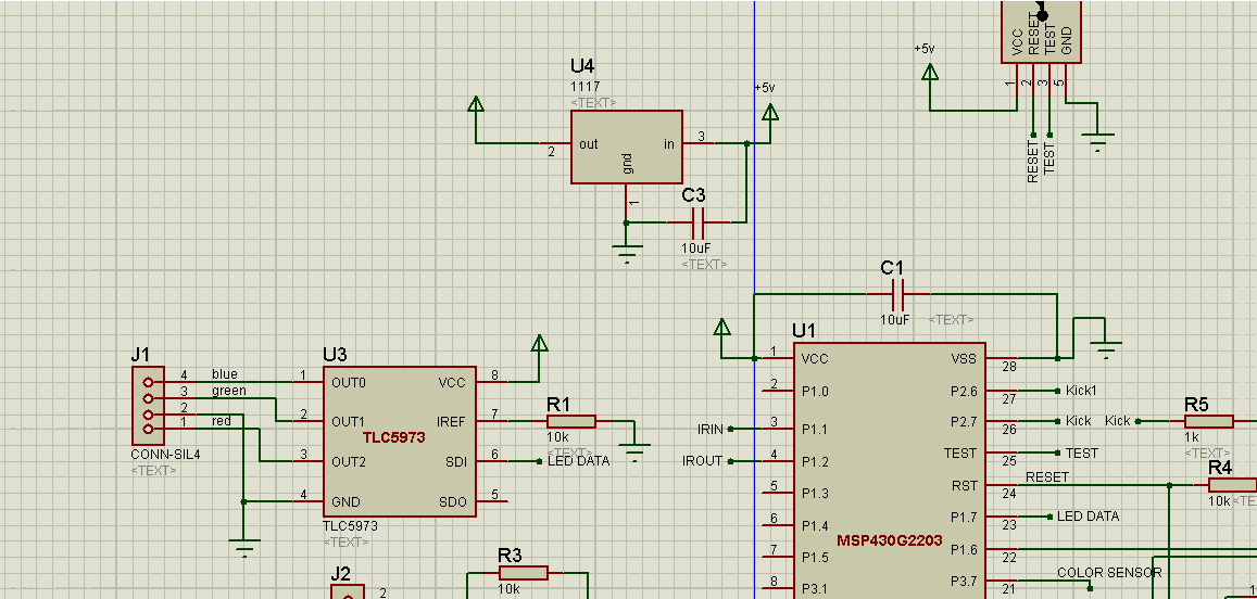
Could you please help me to debug the error when i try to communicate with TLC59731 by single wire interface, the controller i use is MSP430G2553,i've check the signal by osilloscope then it looks fairly correct but output on OUT1,OUT2,OUT0 of its didn't changed .My source code and circuit diagram as following:
#include <msp430.h>
#include <msp430g2403.h>
#include "Basic_config.h"
#include "led_driver_interface.h"
#include "initial.h"
/*
* main.c
*/
int main(void) {
Init_Sys();
counter_led_data=0;Red=0;Green=0;Blue=0;
sent_data_to_leddriver();
counter_led_data=0;Red=128;Green=0;Blue=0xff;
while(1){
delay_ms(100);
sent_data_to_leddriver();
}
}
////////////////////////////////////////////////////////////////////////////////////////////////////////////////////////////////////////////////////////////////////////////////////////////////////////////
/*
* led_driver_interface.h
*
* Created on: Feb 28, 2014
* Author: chuyen
*/
//******************************************************************************//
#ifndef LED_DRIVER_INTERFACE_H_
#define LED_DRIVER_INTERFACE_H_
#define command_code 0x3a
volatile unsigned char counter_led_data=0,Red=0,Green=0,Blue=0,d,temp;
//******************************************************************************//
void sent_data_to_leddriver(void){
/*setup timer_A1 for creating the communicated frequency F = 266,667 kHz*/
counter_led_data = 55; // reset counter for new data block.
TA1CTL = 0x0214; // SMCLK, up mode,enable interrupt
TA1CCR2 = 640;
TA1CCR1 = 200; // 60 -1
TA1CCR0 = 645; // create a 1/3 terminal time per period of communication
TA1CCTL2 = 0x0010; // enable interrupt for compare mode
TA1CCTL1 = 0x0010; // enable interrupt for compare mode
}
//******************************************************************************//
// Timer_A1 Interrupt Vector (TA0IV) handler
#pragma vector=TIMER1_A1_VECTOR
__interrupt void Timer_A1_CCR1(void)
{
temp = TA1IV;
switch(temp){
case 2:
d = (counter_led_data % 8);
if(counter_led_data<8){
if(Red&(0x01<<d)){
P1OUT |= BIT7; // create rise pulse
_delay_cycles(4);
P1OUT &= ~BIT7;
}
}
else if(counter_led_data<16){
if(Green&(0x01<<d)){
P1OUT |= BIT7; // create rise pulse
_delay_cycles(4);
P1OUT &= ~BIT7;
}
}
else if(counter_led_data<24){
if(Blue&(0x01<<d)){
P1OUT |= BIT7; // create rise pulse
_delay_cycles(4);
P1OUT &= ~BIT7;
}
}
else if(counter_led_data<32){
if(command_code&(0x01<<d)){
P1OUT |= BIT7; // create rise pulse
_delay_cycles(4);
P1OUT &= ~BIT7;
}
}
//TA1CCTL1 &= 0xfffe; // clear the interrupt flag.
break;
case 4:
if(counter_led_data==55){
P1OUT |= BIT7; // create pulse to start a next period
_delay_cycles(4);
P1OUT &= ~BIT7;
counter_led_data=0;
}
else{
if(counter_led_data<32){
P1OUT |= BIT7; // create pulse to start a next period
_delay_cycles(4);
P1OUT &= ~BIT7;
counter_led_data++;
}
else if(counter_led_data==50){
TA1CTL = 0x0004; // turn off timer_A1
counter_led_data = 55;
}
}
break;
}
}
//******************************************************************************//
#endif /* LED_DRIVER_INTERFACE_H_ */