This thread has been locked.

If you have a related question, please click the "Ask a related question" button in the top right corner. The newly created question will be automatically linked to this question.

TPS54360 problem

Other Parts Discussed in Thread: TPS54360

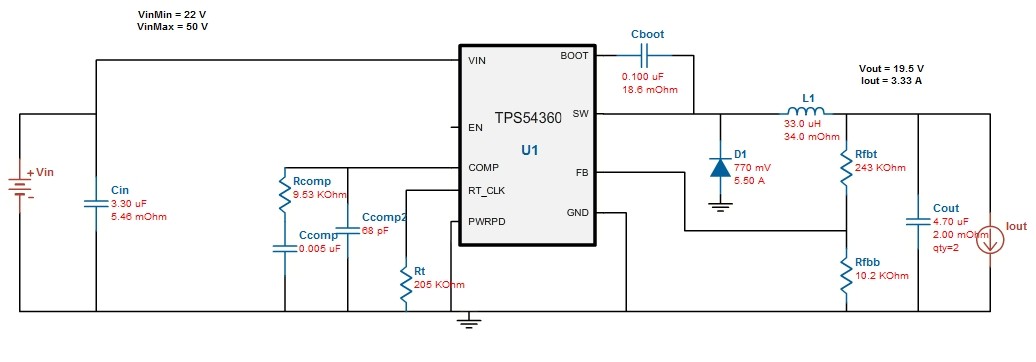
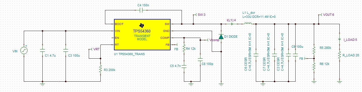
I have built a circuit with TPS 54360 (Vin=24V; Vout=19.5V, Rload=20Ohm) under the guideline of WEBENCH. All the elements have been taken care of with proper margins of error.

The problem is that the swiching frequency is about 40kHz while it is set to be 500kHz by placing a resistor of 200kOhm between the Rt/CLK pin and  the GND pin . And the fact is that the 40kHz is even below the lower limit of of the device.

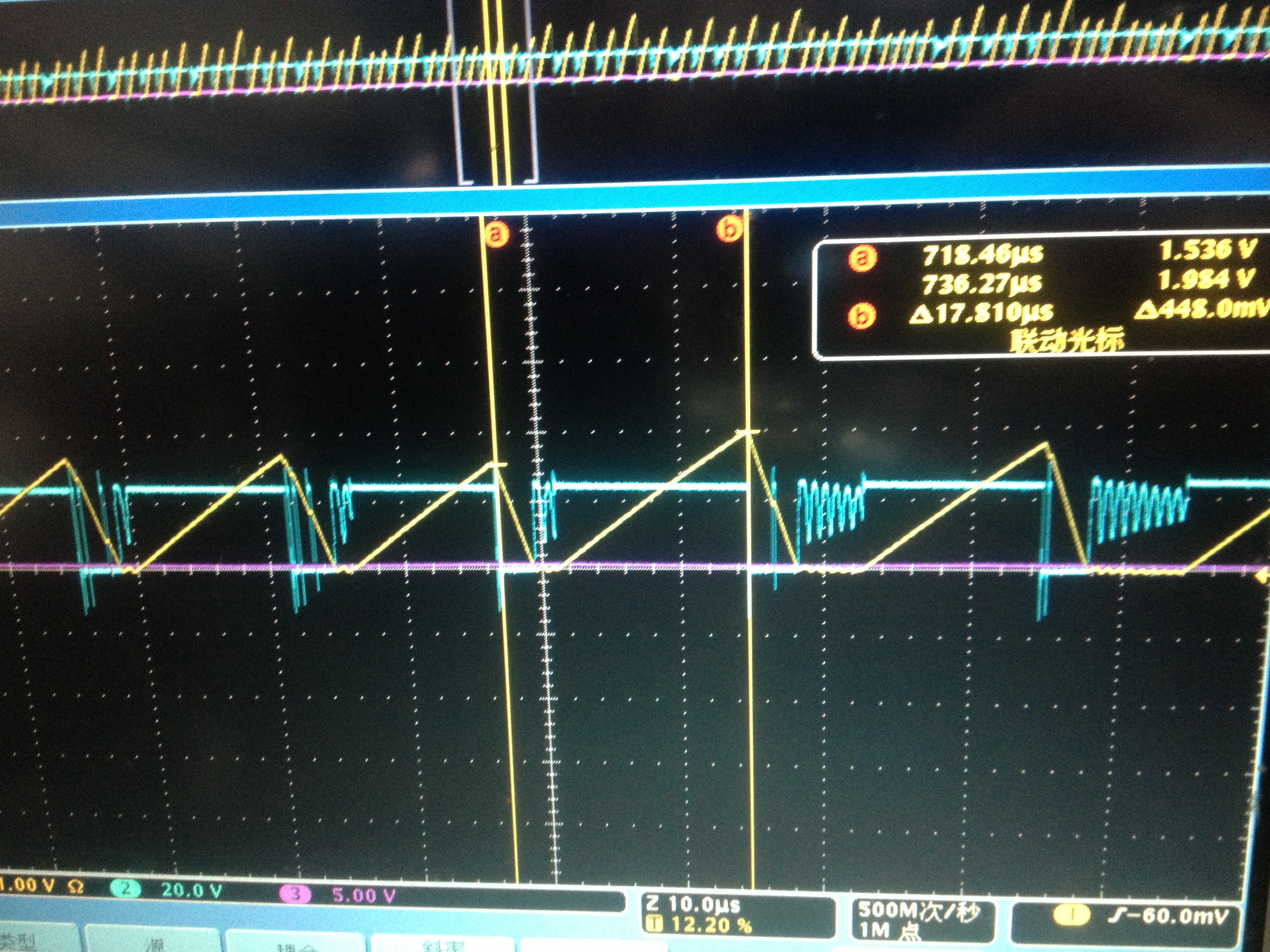
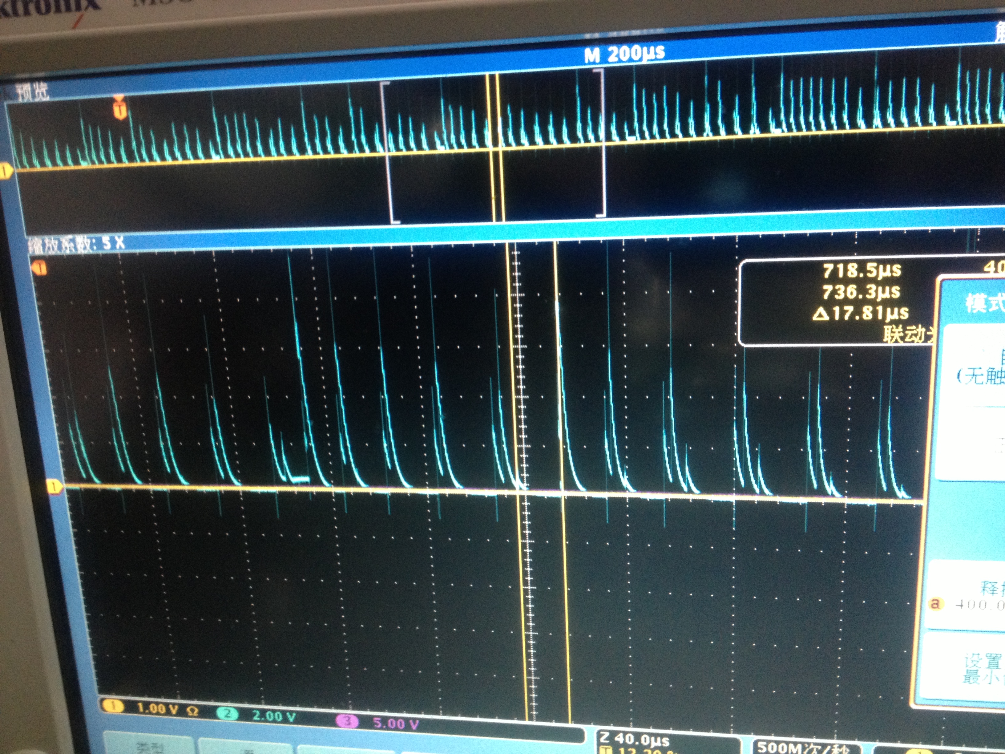
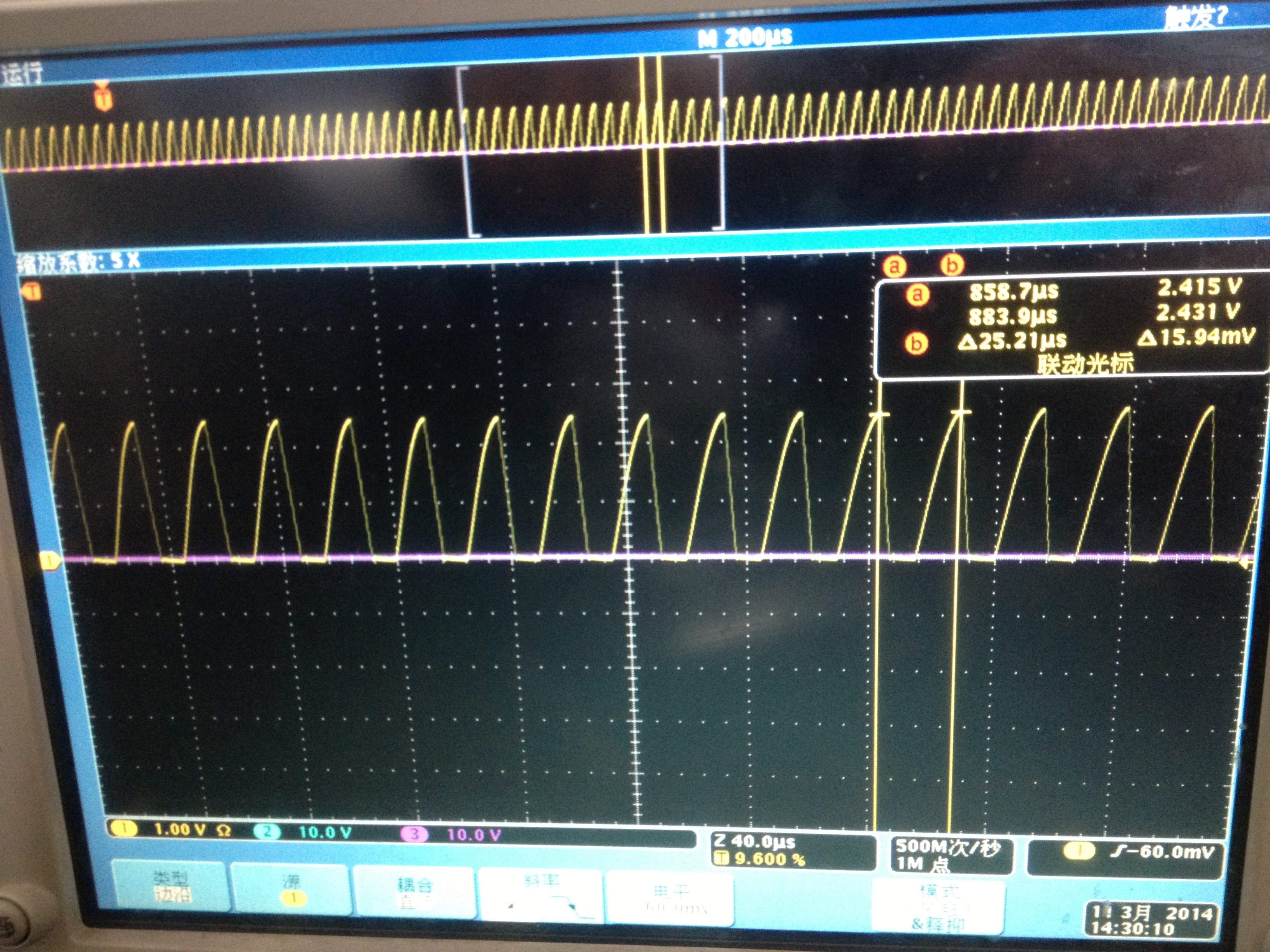
The inductor has to work in DCM as shown in the following figure:

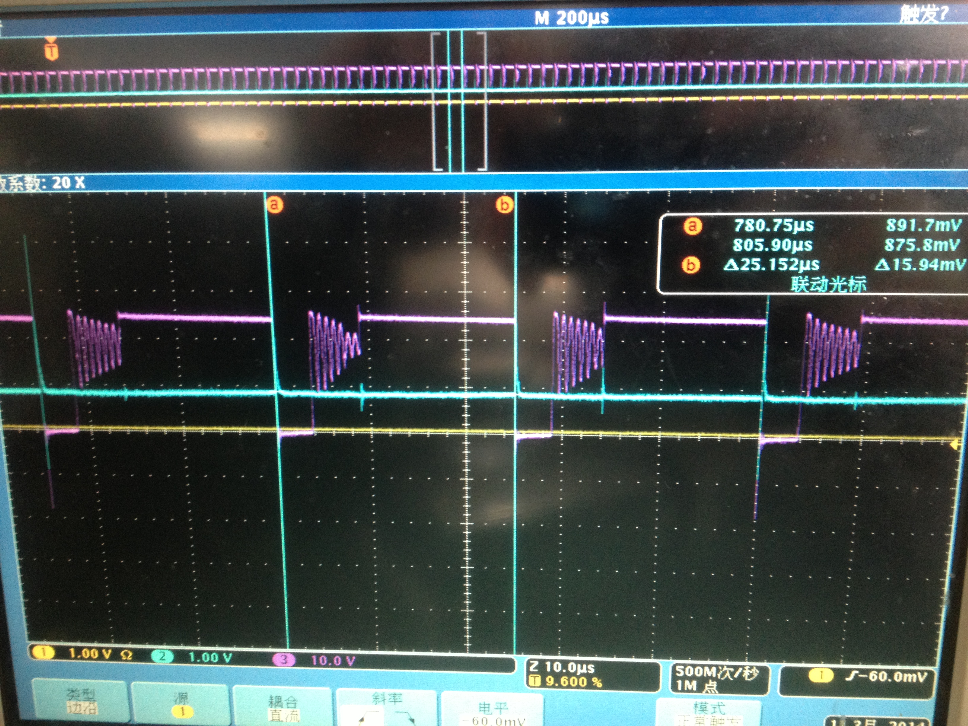
and the SW voltage is as follow:

And I have noticed that during the operation, there is no voltage detected at the RT/CLK pin, while it is supposed to be about 0.5V. 

PS: there is no connection problem

  • Hi Tong,

    This is quite unusual. The behavior you are seeing looks more like the RT/CLK pin is open circuited because of the very low switching frequency. If RT/CLK is shorted to ground the switching frequency is very high.

    Could you replace the TPS54360 and see if there is any change in behavior?

    Also could you share the WEBENCH design report and the layout if it is a custom board?

    Anthony

  • Hi Antony,

           This is the schematic of WEBENCH

    this is the actual circuit

    I have noticed that the resistance between the RT/CLK pin and the GND pin (after the chip was removed from the circuit )was a little different from it had been yesterday( changed from 370 kOhm to 530 kOhm), resulting in the change in switching period from 25 us to 18 us.

    Then I replaced TPS54360 with a brand new TPS54360Q (since TPS54360 was run out of, and the two seem to be almost the same). And the resistance between the RT/CLK pin and the GND pin (before the IC was connected) is about 3.6 mOhm. The peripheral circuit and the layout remained the same.

    It turned out that the frequency remained abnormally low, and the switching period was not constant.

    IL(YELLOW)/SW(BLUE)

    and there were spikes at the RT/CLK, in stead of NOTHING in the previous test with TPS54360

    And it had some trouble with heat dissipation, giving out some noise which had NOToccurred with the previous TPS54360. I has been using "universal board" for the test, which may be a little problematic for the heat dissipation. But the major problem now is FREQUENCY.

    Thank you for your prompt answer.

  • The design looks reasonable.

    What does the layout of this universal board look like? If you have an EVM it would be worth checking these units on an EVM to see if they perform correctly. This will help determine if it is a layout/schematic issue.

    Also what happens if the input voltage is increased?

  • Hi,

    The response of the circuit seemed to be the same when the voltage was increased within the proper range, but the frequency continued to be abnormal.

    Anyway thanks for your replies, and i may consider have an EVM board for further tests.