This thread has been locked.

If you have a related question, please click the "Ask a related question" button in the top right corner. The newly created question will be automatically linked to this question.

LM5088 Gate Drive

Other Parts Discussed in Thread: LM5088

Hello,

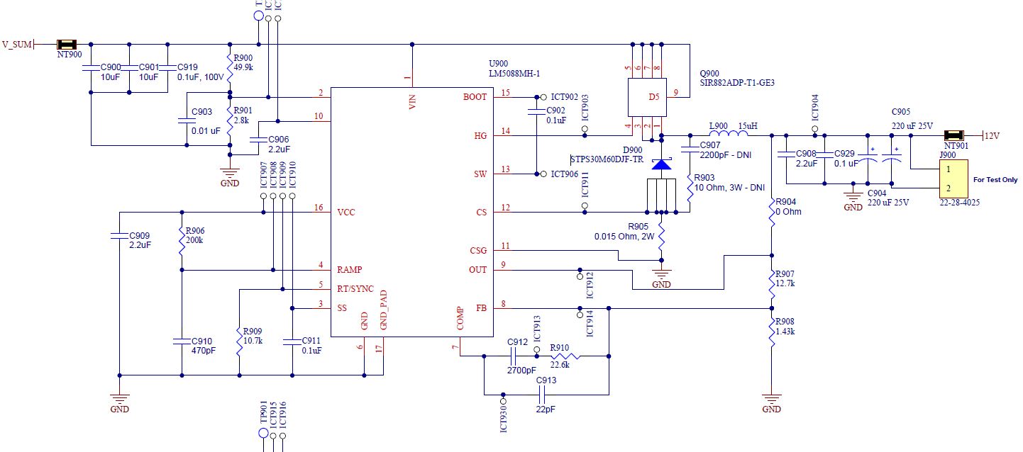
I am trying to reduce the ringing at the output of the regulator by shaping the gate drive.  However, when I add a 40 ohm resistor between the HG pin to the gate of the mosfet, everything becomes unstable.  The ramp signal looks very small, the frequency and duty cylce are all wrong.  The input capacitance of the FET is about 1975pF.  The circuit did work with a 20 ohm gate resistor.  What is the limiting factor?

Thanks,
Ron

  • Hello Ron,

    The instability that you are seeing might be a result of limiting the gate drive too much for the preprogrammed deadtime in the controller.

    Can you post a schematic and provide the switching frequency and FET part numbers?


    It would also be interesting to see you output waveforms with the gate resistors you have tested with.


    On a side note. Have you considered including an RC snubber to manage the switch ringing?

  •  

    Ryan,

    Schematics is shown above.  The switching frequency is 525kHz.  I did try the snubber as in the schematics but I didn't see any significant improvment from it.

    The FET is Vishay p/n SIR882ADP http://www.vishay.com/docs/63367/sir882adp.pdf.  What is the preprogrammed deadtime?  Is it in the LM5088's datasheet?

    The test condition is:

    Input volatge = 28V
    Output voltage = 12V
    load currnet = 2.5A
    No snubber is installed.

    Here is the plot for the gate drive with a 40 ohm resistor (channel 1) and high side of the inductor (channel 4).

    Thanks,

    Ron


  • Hello Ron,

    You want to connect the snubber straight to ground not through the the CS resistor.

    Since this device is Asynchronous (must have slipped my mind) there is no dead-time characteristic because the diode switches when the proper potential exists. However even in this case if the diode has too large of a junction capacitance it will take too long to shut off.

  • Hi Ryan,

    I also noticed the switching frequency switches from 500kHz to 250Hz right before the voltage reaches the final target (12V).  What is causing the switching frequency to change?

    What is the closed loop control mechanism with respect to the FB, OUT and CS/CSG inputs (and maybe the ramp signal)?  I am seeing the ramp signal being a lot higher than normal in some switching cycles.

    Thanks,

    Ron 

  • Hello Ron,

    The LM5088 is most likely leaving the Soft-Start region of the start up. It is potentially using a higher switching frequency thereby transfer less power each cycle to increase the linearity of the start-up curve.

    -Monitor the SS pin and the if the frequency transition occurs when the reaches 1.2V this is most this should clear up the cause.

    The Ramp Signal is dependent on the load current that it emulates. Is there a correspondingly high load current during these switching cycles?

  • Ryan,

    Yes, the frequency switches when it is leaving SS.  However, I am using a 10.7k to set the frequency to be 525kHz.  My question is what would casue the PWM frequency to be incorrect (or change).

    Thanks,
    Ron

  • Hi 

    I reviewed your schematic and found SW pin is not connected to the source connection of your high-side MOSFET. This might be the root cause. 

    If any other electrical connection to ICT908/909, switching frequency can be changed. 

    Regards,

  • Hi Eric, Yes, the schematics is missing a connection. I have been testing with a jumper added from the SW pin to the high side of the inductor. Ron