This thread has been locked.

If you have a related question, please click the "Ask a related question" button in the top right corner. The newly created question will be automatically linked to this question.

bq25570 Issue

Other Parts Discussed in Thread: BQ25570

Hello,

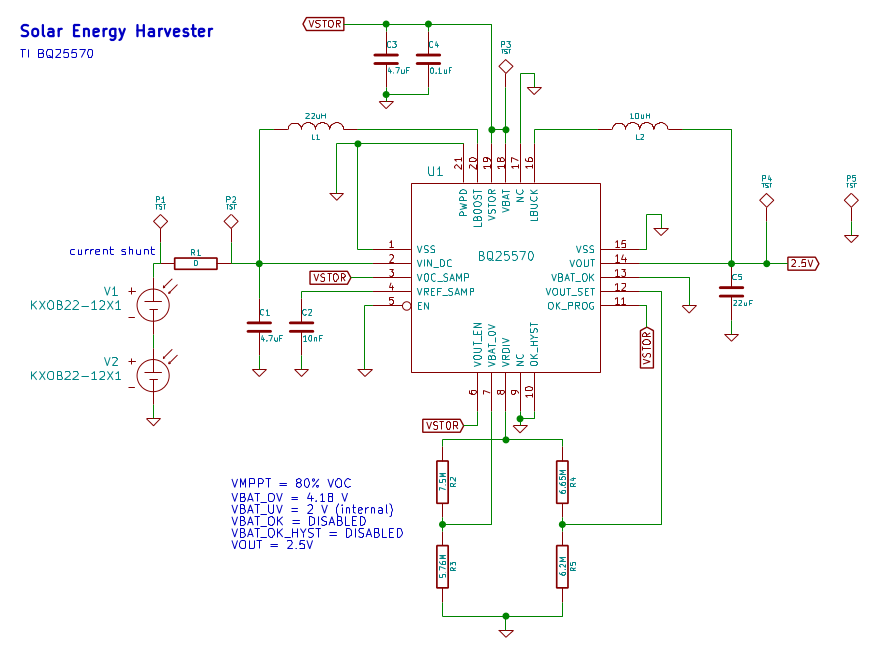
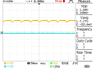
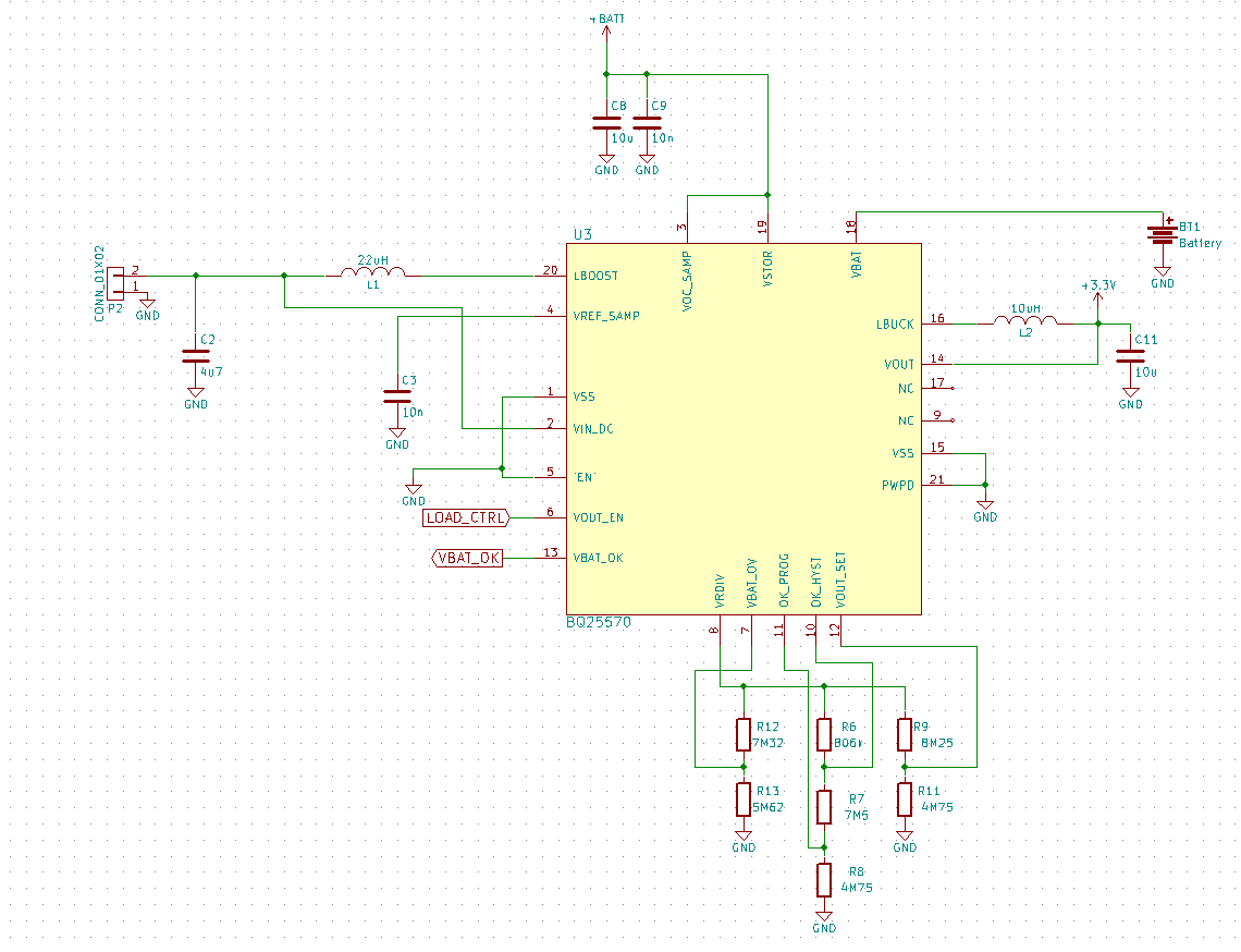
I designed a board using the bq25570. I recently assembled it and am having problems getting it to work properly. I attached a schematic. VSTOR is only charging up to 0.5V. I am not getting anything on VOUT. I am using two solar cells as the power input in a controlled lighting environment which is giving me 1V @ 5mA. I tested this solar input on the BQ25570EVM in the supercapacitor configuration without the supercapacitor attached. I was getting the set voltage of 1.8V on VOUT and a good voltage on VSTOR. So, I verified the solar cells are fine and it seems there must be an issue with the design of my board or an assembly problem. Any idea what could cause VSTOR not to charge up all the way? Please take a look at the schematic and let me know if you see any issues.

Thank you,

-Nick

  • If the supercapacitor is depleted at startup, the IC enters cold start.  In cold start, VIN_DC is clamped to ~ 350mV and the IC itself will need at least 5uW, assuming no load on VSTOR or VBAT, until VSTOR reaches 1.8V.  Your supercapacitor has a DC leakage current that is a load.  It is possible that the super cap leakage is too much for the cold start circuit.  You may need to add a soft start circuit for the super capacitor (i.e., a series resistor that is shorted out after the supercapacitor reaches its voltage). 

    Once out of cold start:

    During assembly, was the board carefully washed to remove solder flux residue that could cause parasitic resistors across your real resistors?  You can measure the effective resistance with a DMM.

    VBAT_OK should not be tied to GND if OK_PROG is tied to VSTOR since VBAT_OK is a push pull output that will try to connect VBAT_OK to VSTOR when OK_PROG=VSTOR.

    With VOUT_EN tied to VSTOR, the buck converter will add an additional load to VSTOR as soon as VSTOR rises above the internal VBAT_UV value.  This may be okay given your high current solar cells.

  • In my test, I did not have the supercapacitor connected. It will be connected to VOUT and charged that way once I can figure out how to get the chip operating correctly.

    If there was parasitic resistance in the resistor networks, would that be able to affect CSTOR being charged up correctly? I'll need to make some measurements to be sure but I thought even if that was the case it would only affect the OV and VOUT settings.

    Hmm, maybe VBAT_OK being tied to ground is the underlying issue. I'll look into that further. Thanks for taking a look and giving your feedback, I appreciate it.

  • The VBAT_OV and VBAT_OK features do not function during cold start.  So, that is not current problem since you are not exiting cold start.  However, it is possible that tying VBAT_OK to ground is also tying VSTOR to GND during cold start.

  • I removed the connection of VBAT_OK to GND and that did not solve the issue. I am in the process of replicating my circuit on the BQ25570 EVM as closely as possible to observe the behavior. I tied VBAT_OK to GND and it worked fine. I removed the 100uF capacitor on VBAT since I don't have that on my board and everything still worked. I would like to try tying OK_PROG to VSTOR rather than the resistor divider on the BQ25570 EVM. If that doesn't turn up anything, maybe the BQ25570 on my board was damaged somehow and I could try replacing it.

  • Hey,

    I have a couple updates. First of all, I fixed the previous issue I was having. It turned out that the BQ25570 was not seated properly on the board and some pins were not making good contacts with the pads on the board. I re-soldered that and I am now getting out of cold start. However, now I have another issue. I have verified that this new problem is a design issue, not an assembly issue. What I am seeing is that VSTOR is getting brought up to ~8V and every time VRDIV generates the pulses to measure the resistor divider network values, VSTOR dips more than a volt and then after the pulses complete, rises up to 8V. Also, my VOUT is regulating to ~3V rather than 2.5V.

    In order to determine if this was a design issue, I replicated the circuit on the BQ25570. I removed resistors R6, R7, and R8 and then soldered jumpers so that OK_HYST was connected to ground and OK_PROG was connected to VSTOR. When I did this, I saw the same behavior on VSTOR where it rises to 8V and dips on each VRDIV pulse cycle. The following image illustrates what I was seeing on VSTOR.

    So now I need to figure out why the OK_HYST = GND and OK_PROG = VSTOR settings are causing issues. I am using these settings based off of Figure 5. Typical VBAT_OK Disabled Application Circuit from the datasheet. I looked at Figure 6. High-Level Functional Diagram in the data sheet to see if I could understand what was happening. I am confused by a couple things I see there. The first thing is that the OK comparator - pin is shown connected to the diagram outline which is indicated elsewhere to be ground. If this were the case the comparator would always have the same inputs and the output would never change which is not correct. Based on my understanding of the BQ25570, I would expect the OK_HYST switch to close when VSTOR/VBAT is rising to test against the upper bounds for VBAT_OK and then OK_PROG to close to test against the lower bounds when VSTOR/VBAT is falling. I am looking for more clarification on the operation of OK_PROG and OK_HYST so that I can make the correct design. In my experiments, I connected OK_PROG and OK_HYST to ground which limited VSTOR to ~3.9V and eliminated the dips during VRDIV pulses. While the over voltage point wasn't quite the 4.18V it should have been, it was much closer. Any thoughts would be greatly appreciated.

    Thanks,

    Nick

  • The block diagram is not accurate.  If VBAT_OK is not needed, you will need to ground both OK_PROG and OK_HYST in order to prevent overshoot. 

  • Hi Jeff,

    my problem is that i cannot get out of the cold start and my VSTOR gets clamped at 330mV.

    So you said that the Supercapacitor is too much Load for the cold start and a soft start circuit needs to be added, so that the IC can get startet.

    In my case i am using a LiOn Battery with 3.7V and 2200mAh connected to the VBAT and on the VSTOR i have a BLE MCU connected.

    At the VOUT i have other ICs. The MCU monitor VBAT_OK and  VOUT_EN and shut down the power if necessary.

    This is my circuit:

    What am i doing wrong?

    This is my solar panel: ixapps.ixys.com/.../SLMD121H04L_2016_06_22.pdf

    Regards,

    Michael

  • If you will always be attaching a partially charged battery to BAT before solar panel is attached (and while VSTOR & VBAT < 200mV) then you fall under section datasheet 7.4.3. The battery has 45ms to charge VSTOR > VSTOR_CHGEN through the battery FET. If that doesn't happen, then the charger enters cold start. When you say VSTOR is clamping to 330mV, do you mean VIN_DC? How much load current is the MCU pulling? You might want to put a PFET in series between MCU and VSTOR, driven by inverted VBAT_OK signal, so that there is no loading on VSTOR until VSTOR > VBAT_OK_HYST.

  • Hi Jeff,

    yes i mean VIN_DC is 330mV and VSTOR is around 1.2V

    The MCU does like 5-2mA at initialization and 100uA while advertising and sleep mode 1uA.

    So the MCU is too much load at beginning, but why isnt the battery charging VSTOR then? The battery is full and the voltage is 3.7V

    When VBAT_OK is HIGH and drives the gate of the PFET, it will open the circuit between VSTOR and MCU.

    Does the VBAT_OK signal tells when VSTOR is good to be loaded by putting it to HIGH? If so, should i use a NFET instead?

    Thanks,

    Michael

  • Hi Jeff,

    what is VSTOR for? 

    Becouse i want my MCU to be functional even if the VBAT_OK and VSTOR are not available so i think i should connect my MCU directly to the battery instead on the VSTOR. In this way i dont have any load on VSTOR. But what about VBAT does it influence the coldstart too?

    The MCU can measure the voltage from the battery and when it reaches the critical value i can power off the Batt and VBAT_OK can wake him up again if battery is ok to be laoded again.

    Thanks,

    Michael

  • VSTOR powers the charger itself and is intended to power the system. VBAT_OK is only an indicator of the state of VSTOR voltage. It has no control over internal charger functionality. VBAT_OK was intended to be used to turn on the system, connected to VSTOR. If your system can't be put into sleep mode or shut down using VBAT_OK then I recommended adding an external PFET driven by an inverted VBAT_OK signal. You can't use an NFET because you would need a drive signal higher that VSTOR to turn it on.
  • Hi Jeff,

    so i connected the MCU directly to the Battery and now it works. The BQ25570 gets out of the coldstart.
    So if i understood it rigth, the VBAT_OK says that a Load can be connected/disconnected to VSTOR but it doesnt give me the battery status.
    So if VBAT_OK is LOW the MCU goes into shutdown mode which consumes 100nA and it will only wake up if VBAT_OK is High again.
    That will prevent the battery from overdischarged.
  • VBAT_OK tells you if VSTOR is within the OK thresholds you set. (I agree not the best choice of naming). When PFET between VSTOR and VBAT is on, VSTOR=VBAT. Tying your load to battery is okay if the battery has its own protector that will prevent overdischarge. If not, then you need the PFET in between VSTOR and BAT to prevent over discharge, with system attached to VSTOR.