This thread has been locked.

If you have a related question, please click the "Ask a related question" button in the top right corner. The newly created question will be automatically linked to this question.

TPS65100 does not regulate

Other Parts Discussed in Thread: TPS65100, TPS65101

Hello,

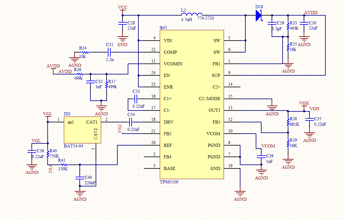
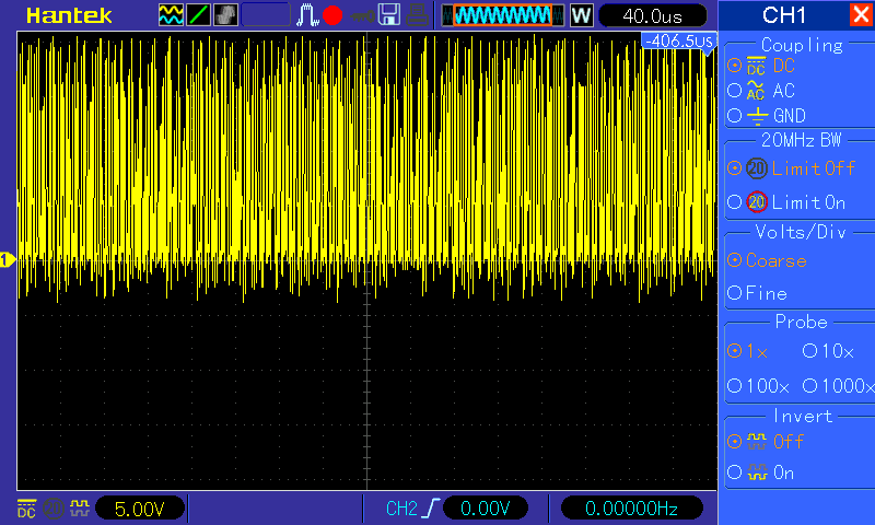
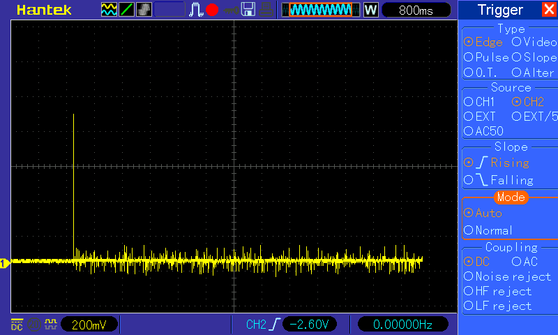
i've designed a board to control a LCD display and I'm trying supply it with TPS65100 IC but i can't get it working (I attach schematic). When I turn on the board, AVDD  rise to near 10 V but then it fall down and it seems that the IC stops regulating. I read documentacion several times and I can't know where is the problem. 

Can TPS65100 works without load? Should really thermal pad be connected to PGND? I forgot to connect it in the design but then I connected it with a wire and it still not working.

Input voltage is 5 V. AVDD should be 10.64 V, VGL -7 and VGH 16.

Thank you very much.

  • Hello Adrian,

    Please check the connection of FB2. I seems that you connected FB2 to REF and therefore FB2 is too high (should be at GND level when the output is in regulation), indicating a short on VGL and then the IC will shut down because of the protection feature.

    You need to connect FB2 between R25 and R27.

    Best regards,
    Brigitte

  • Hello,

    sorry, I've already realized of that fail before I post last message. I routed FB2 between R25 and R26 and it still shutdown. Thank you very much for your reply

  • Hello again, 

    I've measured signals in differents points of the circuit.  I saw that it regulate between 2 and 5 seconds and then it shutdown. 

    In the first seconds in SW i can see rectangular signal of 9.44 V peak and between 1.7 and 2 MHz.. Then the signal stop oscillating. Once the IC stop regulating the voltage levels are: 1.09 in FB2, 1.23 in REF, 0 in FB3, 1.93 in VCOMIN and 350 mV in FB1.

    I wish this information could help you. Thank you very much

  • Hello Adrian,

    Did you check the fbn connection?

    Best regards,

    Brigitte

  • I have checked all FB connections with a polymeter. FB2 between R25 and R27, FBq between R19 and T20, FB3 between R24 and R26. Voltage in this pins are FB1 350 mV, FB2 1.09 V and FB3 0V.

    I tried also to remove C22 and the behavior is the same.

    Is it possible the IC was burned because I turned on it without the thermal pad connected to GND? What is the behavior of the IC if the thermal is disconnected?

    Thank you very much,

    Adrián

  • Hello Adrian,

    As long as you do not have a load connected the part will work normal even if the thermal pad is not connected. The thermal pad is just there to help dissipating the power, it does not have an electrical functionality.

    I expect that you measured the above feedback voltages when the outputs were already turned off, is this correct?

    When you mention that the part regulates for 2 to 5 seconds, there must have happened something causing the protection to kick in. 2 to 5 s are for a switch mode supply really a long time and if it regulates that long, it cannot be a startup issue.

    When you check the part, is there already load connected? I expect that the display is already connected when you start the board. Is there a possibility to check the circuit without the display connected? If not, it is important to get a scope shot of the shutdown moment to decide which output is overloaded causing a shutdown of the device.

    Another possibility would be to check the circuit with TPS65101 which does not have the shutdown feature. If you could exchange the TPS65100 with TPS65101, just the output with a problem would shut down and then we could concentrate on solving this issue.

    Best regards,
    Brigitte

  • Hello Brigitte,

    I had never connected any load. All measurements was done without load.

    I've just set up in another board only the TPS65100 part and it's working, so I think there is something wrong in the other board (not design neither IC) or something in conflict with the rest of the PCB. I'm going to try to know what is worng in the other board and then i write it down here, in order to help and close this threat.

    Thank you very much.

  • In the comment thread, the FB2 miswire is noted in the wrong location; however, I see Pin 20 REF connected to ground and in the Fig 24 typical application, REF should be on the other side of the cap between Rx and Cy.  

  • Hello again,

    last year i've got similar problem and after all issue was resolved, but I didn't know how. I change several times IC and check in differents PCB and it start working. I've mounted then more than 10 PCBs with this design and It's work without problem.

    Now, i've redesing the PCB (i keep schematic wihtout modification) and again I've got same problem.  IC starts regulating and after 200 ms it stops. I can see all signals has been stopped but I don't know with one has the problem.

    Could anybody help to find the problem? Thank you very much.

  • Hello Alvarez,

    Can you attach a scope of all the COMP- Pin, VGL and SW- Pin? In the schematic i cant find anything suspicious, so i need to know more about the application. Do you append a load on any of the outputs?

    Thanks,

    Best Regards,

    Ilona

  • Hello Ilona,

    thank you very much for your reply. There isn't load on any of the outputs.

    I attach a screenshot of all the signals.

    This is SW-Pin

    This is sw-pin detail.

    This is VGL

    And lastly COMP

    Thank you very much

  • Hello Alvarez,

    It looks like it is not switching properly and it seems that the inductance is saturating. Can you tell me what Inductance you are using? Did you check if your power´- components are working fine (rectifier- diode, inductance)?

    Thank you,
    Best Regards,
    ilona
  • Hello,

    It is mounted an inductance of 3,3 uH (7447745033 from Wurth Elektronik). Is the same I'd mounted in the other PCB and it works. I've already change inductors from one PCB to another and the behavior is the same.

    I connect an extern supply directly to C16 capacitor.


    Thanks

  • Hello Alvarez,

    Did you solve this issue or is it still topical?

    Regards
    Ilona
  • Hello Alvarez,

    Did you solve this issue? We will be very thankful if you can share with us your experience.

    Thank you.
    Best Regards,
    ilona