This thread has been locked.

If you have a related question, please click the "Ask a related question" button in the top right corner. The newly created question will be automatically linked to this question.

Using solar and Li-Ion/Li-Po battery as power source for system (0.5A normal, 2.5A peak)

Other Parts Discussed in Thread: TPS62273, BQ24070, BQ24071, TPS63031, TPS63000, TPS63010, TPS5420, TPS54231, TPS54160, TPS54620, TPS54332, TPS63030, TPS54331, LM2596, BQ24705, BQ24610, BQ24103, TPS61175, TPS61170

Hi,

I am new to TI products.

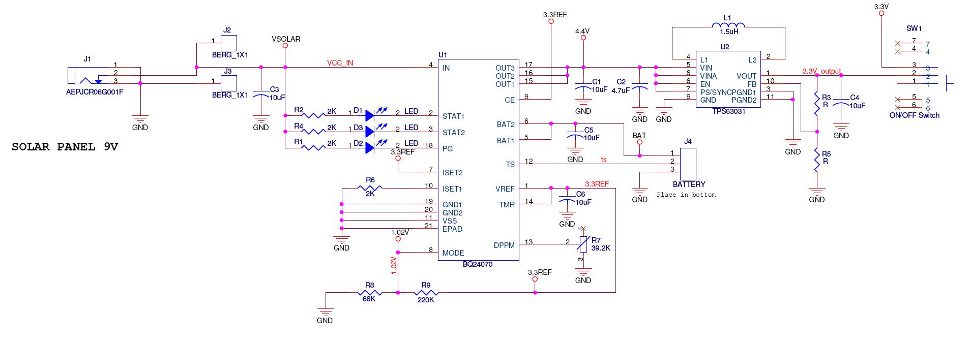
I am designing the power supply module for my application, a standalone one. So it just use solar power (solar panel + Li-Ion/Li-Po battery).


My system needs both 4.4V and 3.3V. So, I decided to use BQ24070 and TPS62273 (400mA for 3.3V source is okay).


Some requirements:

-  The normal total current of system when it actives is about 0.5A and (0.5+2) = 2.5A peak. (Generally, the power demand of system when it actives is larger than solar panel's capacity)

-  4.4V source (VOUT from BQ24070) must between 3.4V..4.5V at all times (including peak current)

The problem is I have no experiment in designing with these devices. So would you mind checking my design for me if it is okay with my application or not?

Somethings I wonder in this design:

- Input voltage in MODE pin of BQ24070 (for selecting high level). I have to use 3.3V reference from itself to make a 1.02V reference. Is this okay?

- Input voltage in ISET2 pin of BQ24070 (for selecting high level). I used VOUT for this.

- Inductor's value for TPS62273 is 47uH, is this suitable?


I have attached it in this post:

6545.SCHEMATIC1 _ PAGE1.pdf


Thanks in advance!

  • MODE and ISET2 are digital inputs that are usually controlled by a micro-controller.  They should be set either high or low (high for your application).  A high could be the 3.3V provided by the IC or Vin if it does not go above 7V.  Along with CE, they should not be powered from the output of the IC as the output voltage may not be there--in the case of no battery or dead battery.

    The TPS62273 is optimized for use with a 2.2uH inductor.  It requires an inductor between 1.5 and 4.7 uH.  47uH is far too big.

    Also, your DPPM level is set too high--4.5V.  The IC will output 4.4V.  Since this voltage is below DPPM, the IC will never charge the battery and will always be in DPPM mode.  You may want to use the bq24071, which regulates to 6V.


  • My application also has a microcontroller, but it gets power from TPS62273. That means only when BQ24070 operates and provides 4.4V, the microcontroller can control MODE and ISET2 pin. Is this okay?

    According to BQ24070's datasheet, VIL for MODE input is 0.975V-1.025V (typ. 1V) and VIH for MODE input is VIL + 0.01 to VIL += 0.024. That means voltage on MODE pin should not exceed 1.025+0.024=1.049V. So can I use 3.3V-7V for this pin to set it to high level?

    My application don't use any extra power except solar power. So I can not find another power source to set CE high. Or you mean that I should use Vsolar for this pin?


    I will change the inductor for TPS62273 to 2.2uH. Thanks.


    Sorry about RDPPM, I almost forgot it when I used reference design for BQ24071 to design my application. I think VDPPM I may need is 3.7-3.8V. So RDPPM here should be 33K.

    I must use BQ24070 when my devices can not operate with 6V, just 3.4-4.5V and 3.3V only:)

  • It doesn't matter what the MODE and CE pins are at if there is no solarpower, as the battery will not charge without an input source.  So, yes, driving them with your uC is ok.

    MODE is a digital input.  The spec for the MODE pin is the spec for the trip points that determine if the pin is read as a high or low.  Per the block diagram on page 8, MODE is compared against a 1V reference.  This is a very precise reference with the tolerances listed in the spec table.  The rating of the MODE pin is shown on page3.

    For generating the 3.3V, you should look at the TPS63031.  This buck and boost converter will allow the battery to go down below 3.3V and yet still regulate the 3.3V that your uC needs.

  • I've tried to read carefully documents related to these devices, and I think the power supply's activities would be:


    * Characteristic:

    - Input:

    1) Solar panel : 9 - 16V / 2.5-5W (150-500mA)

    2) Battery: 3 - 4.2V


    - Output:

    1) 3.4-4.5V output (0.2A normal/ 2A peak)

    2) 2.3-3.6V output (0.5A)

    (My system will become active for each 10s - operation at normal and sometimes at peak current, then sleep for about 30s-2min.)


    * Operation: (With RDPPM = 36K -> VDPPM = 1.15*36*0.1=4.14V)

    - When VSOLAR > 4.4 + VDO(0.5V) = 4.45V, VOUT = 4.4V if system load current do not exceed solar panel's capacity. Otherwise, VOUT = VSOLAR-0.5V.

    - When VOUT is lower than VDPPM, BQ24070 will be in DPPM mode. That means it will try to supply power for system load and reduce charge current until VOUT is lower than VBAT.

    - When VOUT<VBAT: VOUT = VBAT.


    So, VOUT will be from 2.5/3V (VBAT min, depend on the battery) to 4.4V.

    If the solar panel can not provide enough current for system load even at normal, VOUT will usually be equal to VBAT.


    I can use VOUT for the first output, but the second output is impossible.

    Thanks for your recommendation, I think TPS63031 will be a good choice for the second output.


    But I still have something that I do not know exactly about these device's activity at runtime:

    1. When VOUT of BQ24070 is higher than 3.3V, TPS63031 will be in buck mode. But when VOUT falls to lower 3.3V, it must be in boost mode. Can TPS63031 switch between two mode automatically to ensure that it can always output 3.3V without any interrupt can cause the microcontroller reset?

    I found that you also have other products: TPS63010, TPS63000. Do they have the same function with TPS63031 except the maximum output current (IOUTmax)?


    2. The device that uses the first output will be turn off/reset if the voltage belows 3.4V. That's when the battery is the main power source. But at that time, how many percent of battery's capacity left? Do I need another buck/boost device for this output?


    3. In the BQ24070's EVM user guide, the input voltage is only allowed from 4.8-6.5V while BQ24070 can operate to 16V (according to its datasheet).

    So, is there any problem when I connect solar panel output to BQ24070's VIN pin?


    Please answer and explain these questions for me! (or correct me if I misunderstood about something)


    Thanks in advance!

  • Yes, our series of TPS63xxx devices operate the same except for the output current.  The package is also different on some of them.  They were deigned specifically for your situation--a battery supplying a 3.3V rail.  Thus, they will seamlessly switch between buck and boost mode.

    It depends on your specific battery, but I would except there to be significant energy left below 3.4V.  I would recommend another TPS63xxx for this output.

    To answer your third question: the bq24070 is rated to 18V on the IN pin.  So, connecting the solar panel directly to IN is ok.  But, you are wasting a ton of power if your input is between 9V and 16V, and the IC will get very hot as it is a linear charger.  I recommend using a lower voltage solar panel--around 4.5V to 5V at maximum power.

  • Thanks for your fast reply!

    It's hard to find a solar panel that has voltage lower than 12V in my location. Maybe I will try to find a 6V/2.5W panel.

    Besides, I will use this power supply for another application in which the supply power source is an vehicle's accu (12V/24V). So the power loss is hard to avoid.

    Maybe I will need a step-down regulator for reducing the IC's temperature in case I can not find 6V solar panel. The regulated output voltage should be 6-7V. This range will be okay for BQ24070, isn't it?

    Could you please recommend a device to do this for me?

  • Yes, a buck converter on the front end, between the panel and the charger, is a good idea.  The buck converter would output around 4.7V to reduce the loss in the charger.  The following parts are rated for >2A: TPS54620 (a new, popular part), TPS54231 (a low cost, simple part), TPS5420 (an older, very simple buck), and TPS54160 (only 1.5A, but a high Vin buck that can handle surges/noise in an automotive environment).

  • Thanks for your suggestion!

    It looks like TPS54620 will be the best for solar application when its efficiency is very high (98%).

    But I can not use it in applications that has input voltage 24VDC. I think TPS54332 (3.5A) will be a good choice. The accu can provide large current, so I don't want the system load get current from Li-Ion battery when the accu is present. Therefore, TPS54160 (1.5A) is not suitable.

    I will design my application again with these new devices.

    Thanks in advance!

  • Hi,

    I want similar type of circuit which you had designed..ie  I need to recharge a 3.3v lithium battery and run my system and source is solar panel(max o/p is 7v)..

    So i decided to use your circuit.

    I want to use Bq27040 connections like this

    ISET1-> solar output

    CE->solar o/p/ micro controller output

    Mode->Solar output

    ISET2->Bq24070 output

    I didn’t understand what is that 3.3_ref..? From where you have drawn this..?

    regards

    chethan

  • Yes, you can use the bq24070 to charge a battery and then use a switcher, such as the TPS63000, to generate 3.3V from the battery.

    The bq24070 has a pin (Vref) which is the output of a 3.3V regulator in the IC.  This can be used as a 3.3V source up to 20 mA.

    I am not sure what you mean by using the 4 pins mentioned above as solar outputs, etc.  ISET1 is an output of the IC.  CE, MODE, and ISET2 are inputs to the IC.

  • Hi Chris,

    My question is.

    Pins CE,MODE,ISET2 are the inputs ,so Can a connect these pins to the output of solar panel(since my solar panel is 1 to 6v)..?  or it should be controlled by microncontroler only..?

    and I'm using TPS63031 to generate 3.3 v ,is this ok..?


    thanks

    chethan

  • CE, MODE, and ISET2 can handle voltages up to 7V max.  Be sure and examine the voltage threshold levels for these digital signals.  CE and ISET2 require at least 1.4V to register a high, while MODE requires just above 1V.  Tying them to VREF would also work.

    Yes, the TPS63031 is a great choice to generate 3.3V.

  • Hi Chris,

    In BQ24070 I did not understand about Autonomous Power Source Selection (AC Adapter or BAT).

    Does it mean automatically it switchs from adapter to BAT when no input..? How it works..?

    Do we need to play with MODE to select this..?


    Regards

    Chethan

  • The IC will automatically keep the load powered if possible.  The MODE pin simply selects a preference of using either USB or AC, if both are present.  Pages 12 and 13 in the datasheet explain this.

  • Hi Chris,

    Hi I have designed the charging ckt using BQ24070.

    My aim is to   design the charging ckt to charge the battery Li-Ion 3.7v 1000mAh (using solar panel as the source input) and to provide 3.3v source (operates from 2.7 to 4v) to the system.

    Attached is the ckt design for the above functionality.

    Kindly verify the ckt and pls let me know about correctness.

    Solar   panel is 7v, 2w

    thanks

    chethan


  • I would recommend buying the EVM for the bq24070 and the tps63030 and modifying those to your requirements.  This would be much simpler, cheaper, and faster than making your own board and would also validate the circuit.

    A few things that I noticed on the schematic:

    As described earlier in this thread, MODE is a digital input.  Just tie it to 3.3V.  Remove the voltage divider.

    Reduce C6 to less than 1 uF, per the datasheet requirements for the capacitor on Vref.


  • Thanks Chris..

    Already I have sent this for fabrication, so some how I have to make this work..

    I hope other than the above changes there is no correction required for  the ckt..

    thanks

    chethan


  •  

    Hi,

    I had to pause this project for a long time because other projects. Now I return to it.

    I have designed a new circuit using BQ24070 and TPS63031. What a pity that I can not use TPS54331 for 4.8V power source. I have to choose another device with lower efficiency for this.

    I corrected the circuit as your suggestions. Besides, I connected status output pins to my uC for reading status of BQ24070. I used 3.3V_REF from BQ24070 for this.

    This pin can supply 20mA (as datasheet said) and hope this will be enough for 3 status pins (~1,5mA for each).


    Would you mind checking the circuit again for me?

    Thanks.


    I attached the schematic pdf file:


  • On the TPS63031, I would recommend increasing the capacitor values, both input and output.  Equation 6 in the datasheet requires an 11uF capacitor for stability.  At 3.3V DC bias, your 5V 10uF will be more like 5uF or even less.  I recommend using 2 x 10uF @ 6.3V for the output and 10uF @ 6.3V for the input.  This is what was used when the datasheet data was taken (page 11 of the D/S).  Lastly, you may want to consider tying the PS/SYNC pin to ground to enable power save mode.  This is typically done in battery powered systems, but depends on your system requirements.

    For the bq24070, you should use 425 for the scale factor instead of 450.

    What is wrong with the TPS54331 in your application?  Do you need higher current?

  • Hi chris,

    I just need information on some ICs,

    Which IC will be the better for the following specs.

    Input voltage is 9v(AC) and I need to recharge the battery of 7v and I should get the regulated output voltage of 6-7v.

    is there any series of BQ IC will do the above operation..? or Can I  use  the BQ24071  ..?

    thanks

    chethan


  • Thank you very much for your corrections.

    I modified capacitor's value and connected PS/SYNC pin to GND.

    About the BQ24070, should I use an 390R resistor on ISET1 pin so that the maximum input current can rise to 2,72A? With this, every time the GSM modem boost the current up to 2A, the external power source can supply all the current my system needs and do not get power from the battery, avoid charging the battery frequently. Though the maximum rating input current of BQ24070 is 3,5A IN and 4A OUT, but the recommend input current is only 2A. I wonder this modification is good or bad for the system.

    I cannot use TPS54331 at present because the price of the external components for it is still high. (1x10uF@25V and 2x47uF@10V ceramic cap, inductor that can operate at 1MHz freq.). LM2596 is my temporary replacement. I hope I can use TPS54331 or TPS54620 in the very near future.

    I attached the corrected schematic. Would you mind checking it again to sure that I modified correctly as your suggestions.

    3288.SCHEMATIC1 _ PAGE1_fixed.pdf

    Thanks.

  • Yes, the schematic looks correct.

    The charging current should be set below 2A, per the recommended operating conditions spec for maximum input current.


  • Chethan,

    I am not sure what your requirements are.  Is the battery voltage 7V?  The bq2407x series is designed to recharge a single cell Lithium-ion to 4.2V.  For other voltages or multiple cells, look at switching chargers, such as the bq24103, bq24610, bq24705, etc.

  • Thanks for your support :)

  • Hi,

    I need to rechrage the 7v li ion battery from the AC source (9v),.. and my other ckt needs regulated 6v.

    ie  I need a IC which charges the 7v li ion  battery and gives some 6-7 reglated voltage ..

    thanks

    chethan

  • Thank you for clearing that up.  I have never heard of a 7V Lithium cell.  Almost all the ones that we deal with come at 4.2V fully charged.

    I recommend the bq24610 for the charger.  It allows you to set the charge voltage at any value.  Most of our Li-ion chargers only allow the charging voltage to be set for a 1-6 cell Li-ion pack, at 4.2V/cell.

    Depending on how much power you need on the 6-7V rail, I would recommend a SEPIC converter.  This allows the input voltage (battery voltage) to go above or below the output voltage and still maintain regulation of the output.  A controller for this would be the TPS61175 (high power) or TPS61170 (lower power).

  • I had a prototype board from the schematic I've attached here before. And it's operated differently with its functions.

    It seems the output of TPS63031 depends on PIC's clock frequency.

    I do not know the reason why it becomes like that.

    I've tested some cases: (at first, dsPICJ128MC706 was soldered. After that, I tried another PIC-dsPICJ128GP706 but the problem still occures)


    Power Sources: VIN -> LM2596 -> BQ24070 -> TPS63031

    - In theory:

    VIN: 12VDC

    V_LM2596 = 4.8V

    V_BQ24070 = 4.4V

    V_TPS63031 = 3.3V

    - In real:

    VIN: 12VDC

    V_LM2596 = 4.8V

    V_BQ24070 = 4.3-4.4V

    V_TPS63031 = <unstable according to PIC's freq>


    1. Using internal Fast RC Oscillator in dsPIC33FJ128GP706 (7.37MHz)

    - V_TPS63031 : 3.4V

    - Led blink normally

    2. Using internal Fast RC Oscillator with PLL to 20MHz or larger

    - V_TPS63031 : 3.6-3.8V

    - Led blink continuously (PIC operates in under 3.6V)

    3. Using external OSC 4MHz

    - V_TPS63031 : 3.4V

    - Led blink normally

    4. Using external OSC 4MHz with PLL to 20MHz or larger

    - V_TPS63031 : 3.6-3.8V

    - Led blink continuously (PIC operates in under 3.6V)

    5. Using external OSC 25MHz

    - V_TPS63031 : 2.5V

    - Led blink with normal frequency but it do not turn off completely (light a little)

    6. Using external OSC 25MHz with PLL to larger

    - V_TPS63031 : 3.6-3.8V

    - Led blink continuously (PIC operates in under 3.6V)


    Would you mind checking it for me? If you need layout or something else, please tell me.

  • This is a multi-stage circuit that needs to be debugged piece by piece.  To do this, look at each output voltage (4.8V, 4.4V, 3.3V) with a scope and see if they are stable.  Another thing to try is to not use the PIC, but simply use resistors as a load for now.  If this power supply can handle resistors and be stable, then the problem is in your PIC.

    If you get frustrated with the PIC, check out our MSP430 line, which is cheaper and uses less power.

  • I've tried 2 PIC and the result didn't change, so I think the problem is not caused by PIC. I don't have a scope until next 5 days so I can't check it carefully. But I want to know is there any possibility that can cause devices operate like that? Why the TPS63031 output normally only when PIC operates at low clock freq? And what cause it raise the output voltage to 3.8V? I just want to know reasons so that I can find out what I have done wrong.

    So, if you know some reasons, please tell me. I'll check the board by a scope and tell you later.

    Thanks.

    P/S: All these devices were soldered by hand. 

  • We need to debug this piece by piece.  Does the circuit work with a resistive load?  Is each voltage in the chain stable?  These are the kind of things to look at.

    The current that the PIC pulls could be changing with operating frequency.  The TPS63031 in your configuration may be unstable at some of these different loads.  Or some of the pins may not be soldered down properly.

    The TPS63031 has a power pad.  Hot air is the best way to attach these parts.  There can be damage when used with soldering irons.  Make sure all the pins, including the powerpad, are soldered down well.