This thread has been locked.

If you have a related question, please click the "Ask a related question" button in the top right corner. The newly created question will be automatically linked to this question.

Bq34z100EVM Problem

Other Parts Discussed in Thread: BQ34Z100EVM, BQ34Z100, BQ34Z100-G1

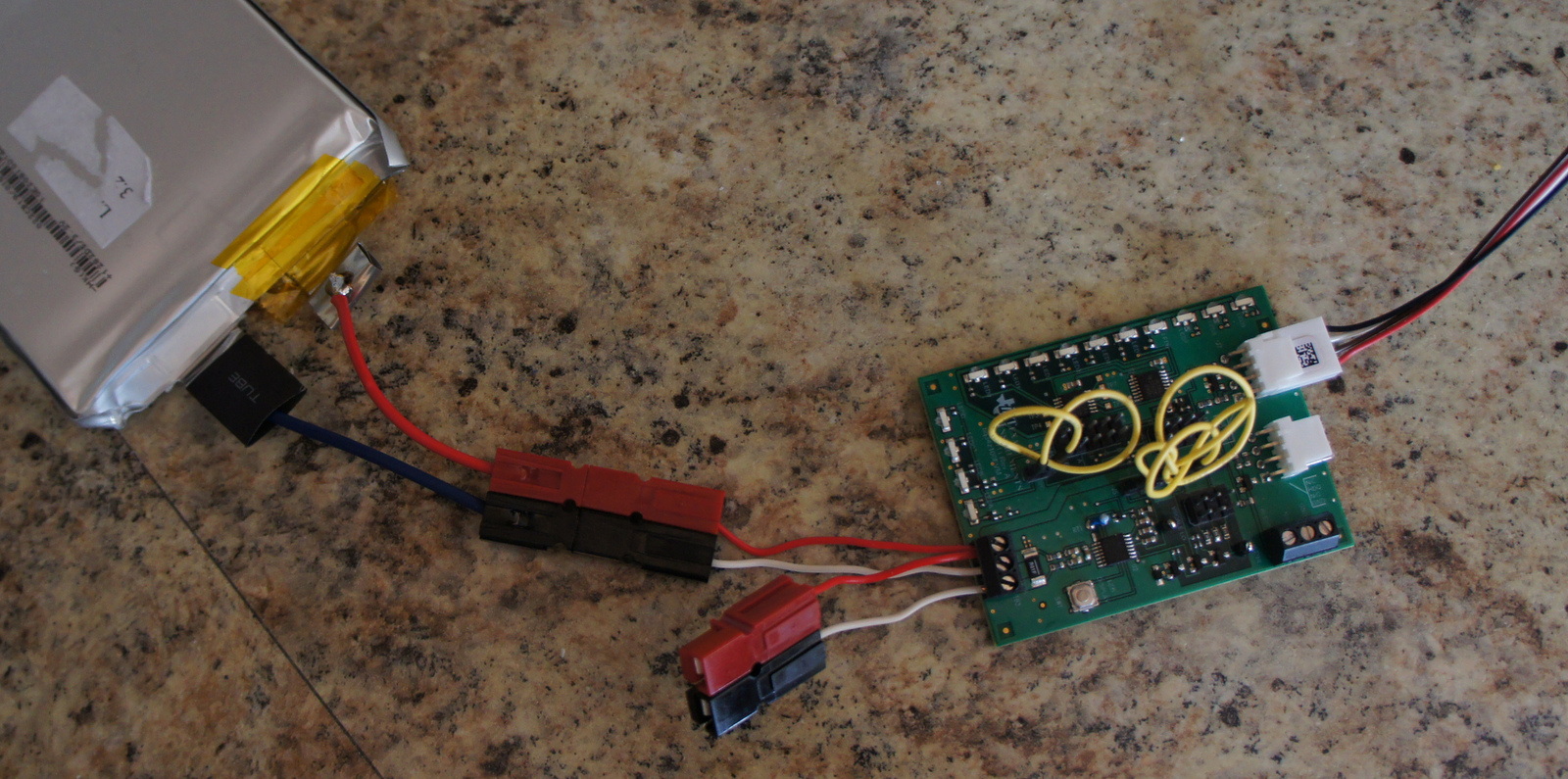
Ok, I'm starting out with the Bq34z100EVM module to try to track state of charge of a single 3.2v - 10 Amp Hour LiFePo4 battery to keep things simple. 

I am using the EV2300 to interface the EVM with my laptop. I'm using the BQ Evaluation software for this board and the software detects the Bz34z100 EVM chip just fine. 

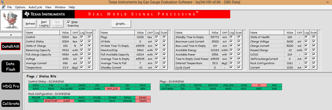
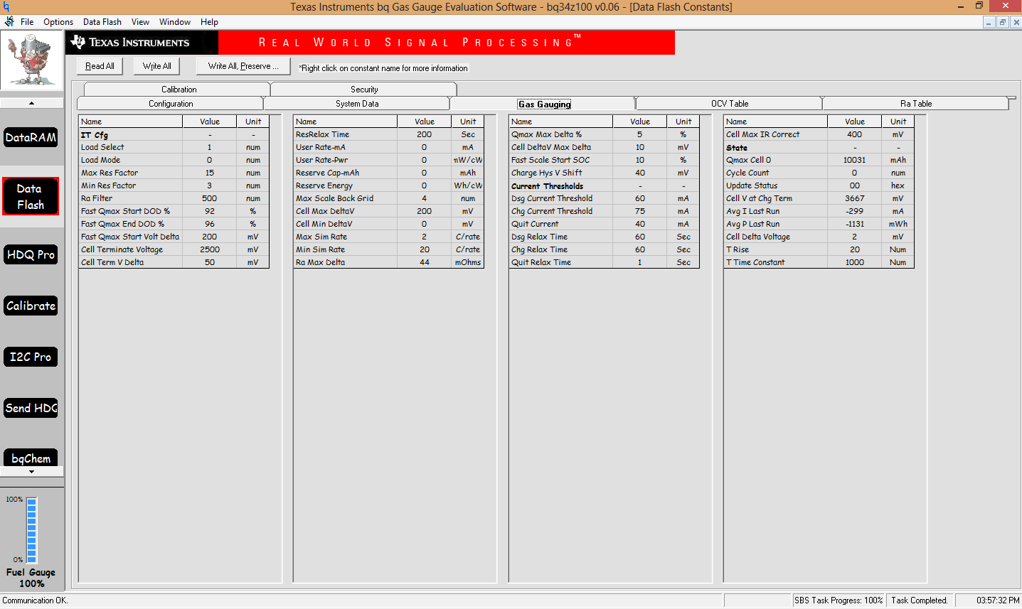
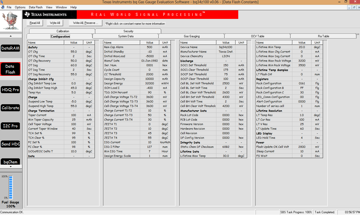
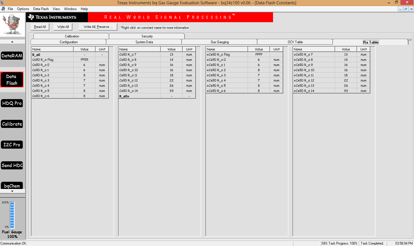
I have been able to program the Bz34z100 chip with my battery data like charge voltage, capacity, taper current, I first loaded the correct Bq battery chemistry profile for the type of battery chemistry I'm using. I have calibrated the chip also. 

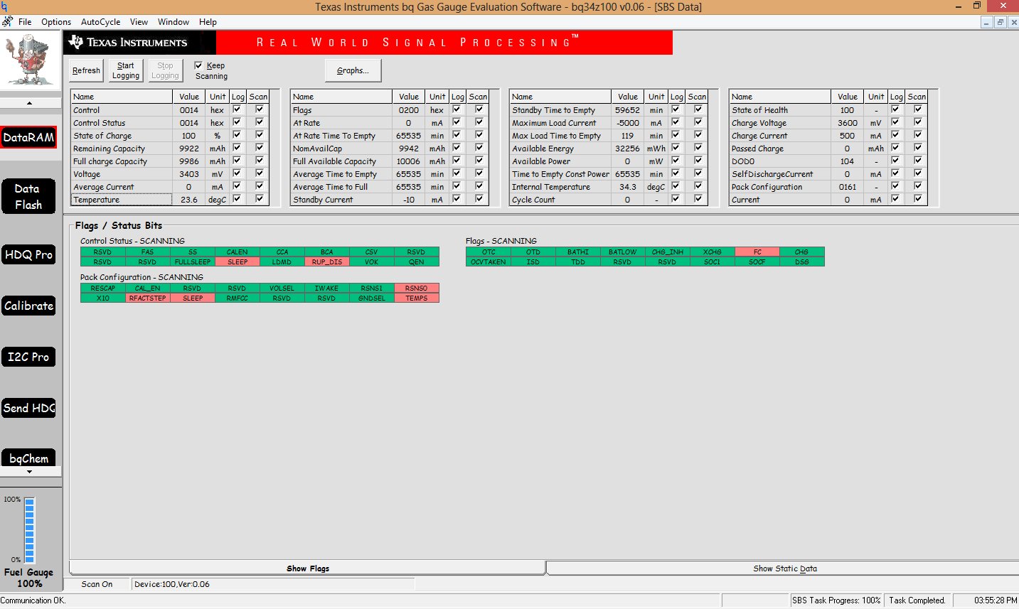
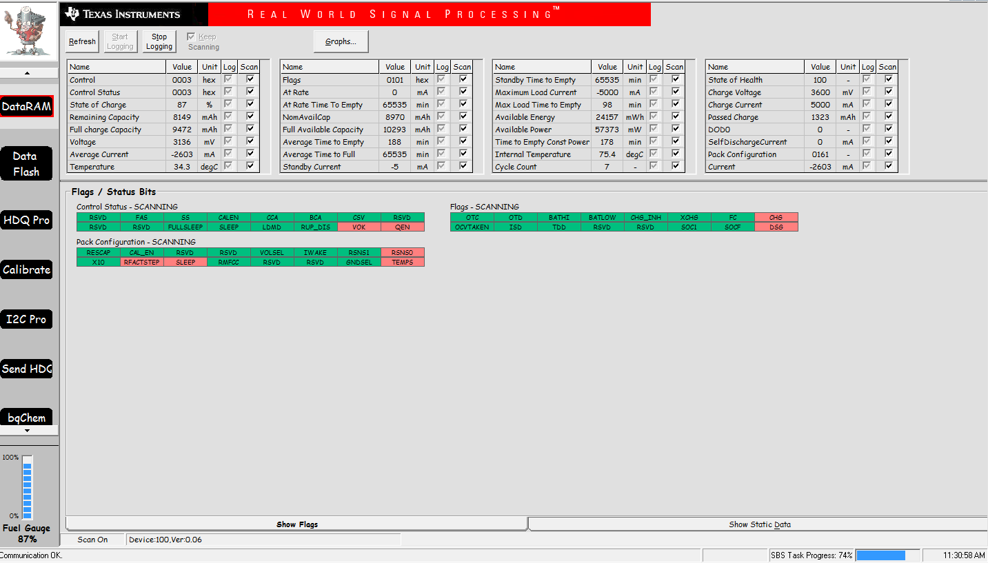
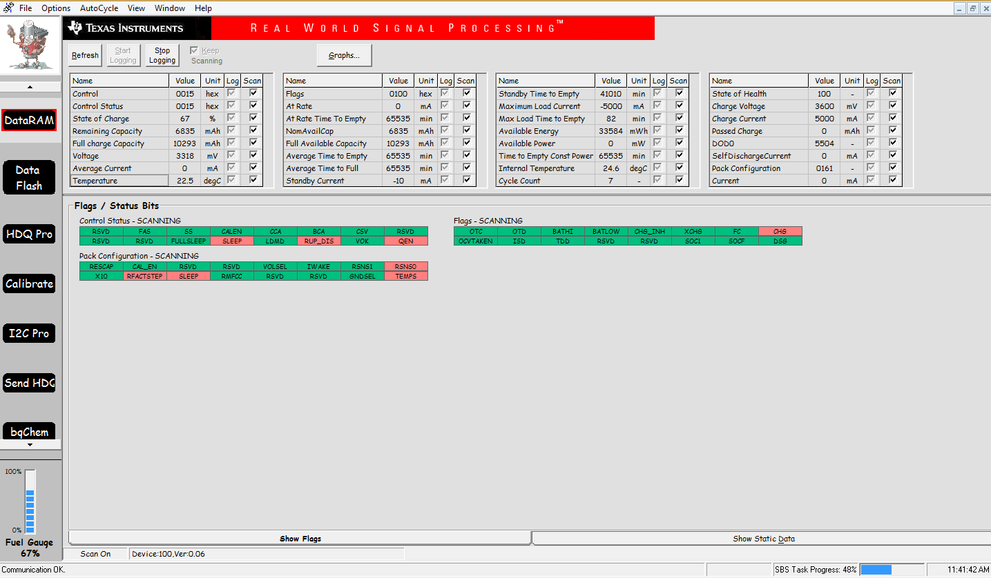
I can charge the battery from a power supply just fine and the software shows the current going into the battery just fine even up to 5 amps of input current. The State of Charge updates to 100% fully after the full charge parameters are met. 

The Reg25 pin is showing 2.5 volts. 

I am having a issue as soon as I try to discharge the battery through the EVM module.Tthe Bz34z100 chip instantly starts getting really hot and eventually stops communicating with the BQ software over the course of 1-2 mins after I plug in a discharge load. This will happen with a 40ma load or a 2 amp load, the same thing happens either way. I have not damaged the chip in any way and it seems I have everything setup right based on everything I have read. 

When it gets hot it will pull about 500 mA @ 3.6v continuously. What could cause this? I'm assuming maybe it has to be  when something notices a discharge current flow and that causes the chip to do something that causes it to heat up? 

After the chip heats up I have to leave it unplugged for 30 mins and then it will begin working again just fine until I try to start discharging from the battery.

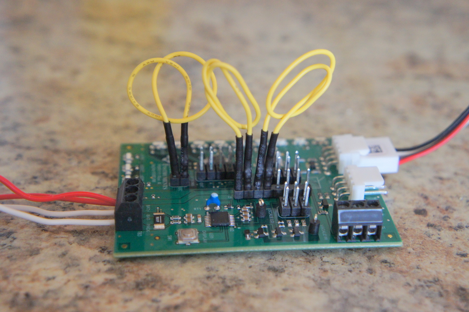
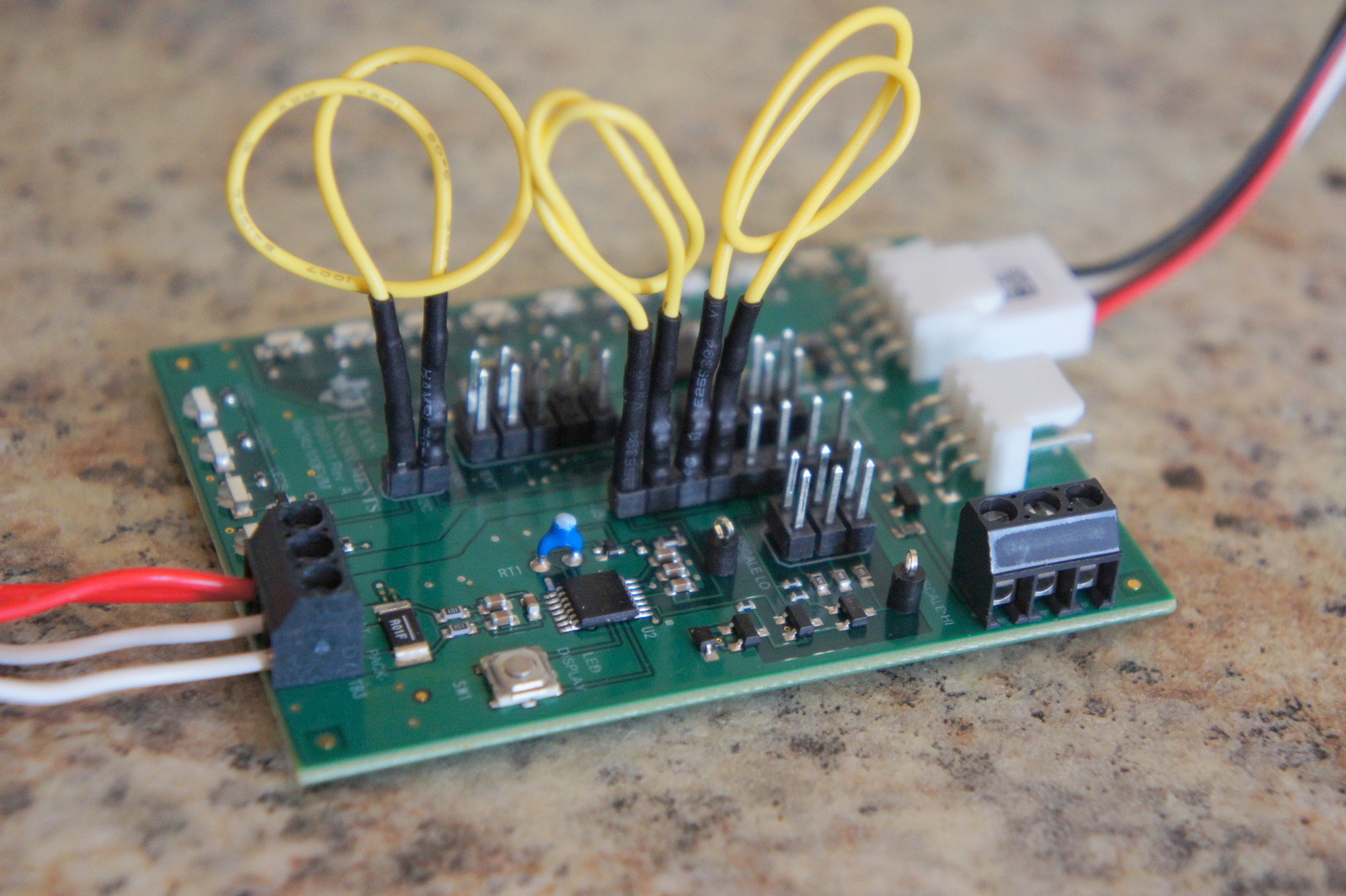
I'm attaching screenshots of the software settings and the board for review, hopefully somebody can catch something if its wrong. everything looks great otherwise. 

  • Any ideas on why the chip heats up and shuts off when I try to pull power from the battery through the sense resistor? 

  • Ryan,

    I do not see anything wrong in your picture and I do not see any issues on the bench with my EVM setup like yours. You must have a defective device. You can export a senc file and I will try it, but I do not see how the setup could cause the device to get hot.

    Tom

  • Thanks for looking it over for me. 

    I have a new EVM  board on the way so lets wait to see if I have the same problem with the new board before doing anything else. 

    Do I need to do a Impedance Track learn cycle on my battery? Is there a learn cycle option with this Bz34z100 chip? I don't remember seeing that option in the BQ software. 

  • Ryan

    You do need to run an optimization cycle on the pack, but that would not have caused the device to run hot. You also need to calibrate the device and enable Impedance Track. Refer to pages 29 and 30 of the datasheet.

    Tom

  • So can you give me a laymans quick run down on how I should do a correct Impedance Track learning cycle with this Bq34z100 chip? I read the explanation in the datasheet but it just tells me how to active Impedance Track via the control command.  

  • Ryan

    The process for running an optimization cycle for this device is the same as for our other IT devices. Please checkout this document on the TI website to see it it helps. SLUA597

    Tom

  • Ryan,

    Your other post seems to have disappeared and I reviewed the parameters. You have the Term Voltage set to 3600mV and this is why you cannot get a capacity estimate. It needs to be set to the end of discharge voltage and this begs another question. You are designing a single cell pack with a LiFePo4 cell, so this is going to limit how low the cell voltage can go. You also need to send the IT Enable (21) command to turn Impedance Track on.

    Regards
    Tom

  • Ok I read that document and it did answer all my questions on how to run the test. 

    I see I started out the wrong way with a fully charged battery. 

    How do I start from scratch with the Impedance Track learning cycle with a discharged battery? 

  • Yea I deleted that post because I got it working by changing the Terminate voltage back to 2.5 volts. 

    At least now I know what was causing the problem now. Thank you. 

  • If your battery is fully discharged and the cell has rested for a few hours, then you can send the IT Enable command and charge it to full. Qmax should update during the rest period after charge. You can then discharge and the Ra table should update and Qmax should update again in the discharge rest period.

  • Makes sense. 

    So should I do this: 

    #1. Start out with a fully discharged battery that has rested for 2 hours. 

    #2. Issue a reset 41 command.

    #3. Issue the IT Enable 21 Command to force the learning cycle again. 

    #4. Follow the recommended learn cycle instructions in the SLUA597 guide. 

    Sounds easy enough. 

     issue a reset 41 command and an IT Enable 21 command to force the learning cycle to start again with a discharged cell that has rested for a few hours. 

  • That should work. Note that you are using a LiFePO4 cells, so the rest period may be much longer after charge and discharge. I have seen it take 24 hours, but hopefully yours will be quicker.

  • Yes indeed it does look like it may take 24 hours for the discharged voltage to become stable. I'm at 17 hours and its still slowly creeping up. 

  • Is there any reason the CHG & DSG flags should be set at the same time? 

    I noticed that the chip on the 2nd evaluation board got up to 75c as soon as I disconnected a load and then reconnected it.

    I saw that the CHG & DSG flags were set at the same time and figured that might indicate the reason the chip is heating up internally. Nothing else has been done that could have caused any damage to the board. 

    I disconnected the battery from the chip and then reconnected it. It no longer heated up but the current is showing 0 but the CHG flag is still set even though the fuel gauge is in Sleep Mode. Is this normal? 

    I did a control 41 reset command a few times but it does not clear the charging flag. 

    I'm hooking up a small 2 amp DC Switching boost regulator that takes 3v and converts up to 5v DC. Do you think that maybe this device could be causing a voltage spike when disconnected or initially connected that could be damaging the IC? 

  • Yes, it is common for the CHG flag to be set. It is defined differently on this device as compared to some of our other devices. It will be set whenever the pack is eligible to be charged.

  • Any ideas on why the chips on 2 different evaluation boards would be heating up like this? 

    If the voltage spiked above 5v when set to 1 cell configuration could that easily cause this issue? 

    Only thing I can think if is that this DC switching boost regulator is pushing out a voltage spike higher than 5v when initially connected or disconnected to the battery pack terminals on the evaluation board. 

    If this is the case would just replacing the Bq34z100 chip fix the whole board or would a small voltage spike above 5v damage other stuff also? I'm not sure if the voltage is spiking above 5v but its really the only thing that could explain why the chip begins heating up like this. 

    I just disconnected the battery from the evaluation board and plugged in the load DC regulator to the battery pack connection on the evaluation board as it should be. Then I plugged the battery back into the evaluation board and this time it did not heat up and its working fine again. Hummm. 

    Voltage spike maybe? Any ideas on what could actually be heating up internally pulling .5 amps @3v without completely killing the chip considering it remains operational and transmitting data? 

    Let me know what you think. 

  • I have damaged these EVMs before by applying too much voltage to the BAT pin. In some cases the bq34z100 gets damaged and we have also seen the FET in the REGIN power path damaged. If you have a specific setup and procedure to induce the condition, then I can try it here. Also, please extract you senc file and I will use it.

  • So if I wanted to fix the first evaluation board I would need to just order a new Bz34z100 chip and what is the part number the FET that might possibly also be damaged? I'll order one of those also. 

    I'm not sure how to get you to replicate the buck dc converter I'm using except to send you one of them. Everything else is pretty standard, just a 3.2 LIFePo4 battery and the EVAL board setup for a single cell monitoring. 

    On the board that is still working, how could I tell if the FET was damaged? 

  • Ryan,

    The FET is located in the REGIN power path and we used a 2N7002. You could use a similar FET that you may have available. It just forms a simple linear regulator.

    Tom

  • Hello Tom and Ryan,

    It seems that I've encountered the same problem :

    On BQ34Z100-EVM, designing to work with a LiFePO4 1S battery (1.4Ah), sometimes the BQ34Z100 crash (stop communication with EV2300) + about 600mA drawing from battery + BQ34Z100 temperature increase.

    It arrive sometime when switching the 5V laboratory power supply for the charge circuit, and sometime when connecting the load...

    As I don't really understand, I was thinking of a BQ34Z100 possibly endamage with first tests, I've replace the BQ34Z100 with a new one on BQ34Z100EVM. But there still the problem.

    Do you find a solution? Or the reason why this problem occur?

    Regards,

    Hubert

  • Hubert,
    Are you saying that the bq34z100-G1 does not communicate after replacing the device or it fails again when the charging voltage is applied? If it fails to communicate, then check REGIN to verify that it is at the battery or charging voltage. Check REG25 to make sure that it is 2.5V. If these are good, then check the thermistor to see whether it is pulsing at a 1s rate. This will indicate whether the firmware is running.

    If REGIN is not at the correct voltage, then perhaps one of the FETs in the shunt regulator are damaged and pulling the voltage down.

    Tom
  • After replacing the BQ34Z100-G1 the device is working well.
    But sometime (last time was when connecting the load), the problem is back (communication crash+600mA current+heat).

    I will try to change the 2N7002.

    Hubert
  • That sounds like one of the pins is going over 0.3V below Vss and causing the device to latch-up and fail. I would try applying a lighter load to see whether this prevents the failure. You can check pins with a scope and see whether signals are going too far below Vss.
  • Hi Tom,

    I've changed the 2 2N7002. But still have the problem.

    I've not try to measure pin voltage, but noticed that the problem seems to come when applying the load while the device come from disable state (I'm using a circuit for driving CE high, when the load is connected).

  • Hi Tom,

    I've measured BQ34Z100 pin and measure a peak on SRN, a little more than 300mV.

    The pack was supplying a step-up and the step-up had a 50µs peak current of about 3A (so, with my Rsns=100mR, sometime goes under -0.3V on SRN).

    When I replace the step-up by a pure resistive load, there's no peak and no problem.

    Now, I've put a filter between the pack and the step-up and the problem is resolved.

    Thanks,


    Hubert