This thread has been locked.

If you have a related question, please click the "Ask a related question" button in the top right corner. The newly created question will be automatically linked to this question.

TPS61040 solution overcurrent

Other Parts Discussed in Thread: TPS61040, TPS61041, TPS61040EVM-001

Hi,

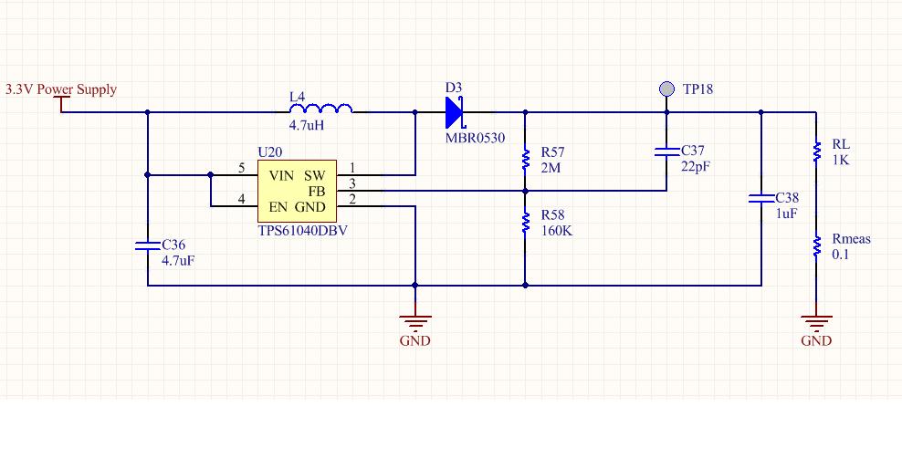
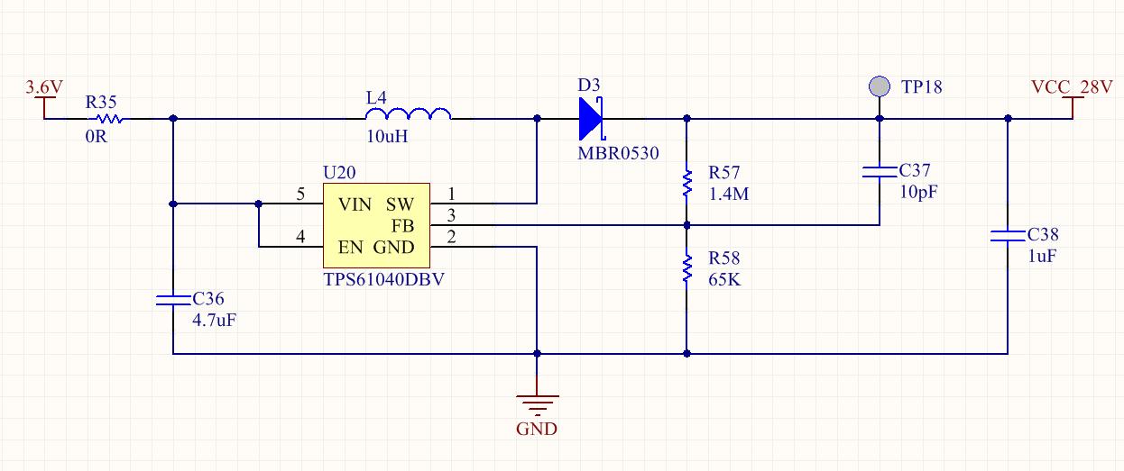
We are using a the TPS61040 for the generation of a higher voltage(28V) from battery. Our configuration is as shown in the picture below. At the output we have the 28V needed but there is an overcurrent. Our calculations give us an Iout max of 19,8 mA. We tested with various Rload and these are the results:

Rload = 22k , I = 16mA

Rload = 5.6k, I= 65mA

Rload = 10k,  I=36 mA

Rload = 2.2k, I=108mA (here Vout drops to 24V)


Can anyone give me any advice on this?

Thanks,

  • You can test the Vout voltage to see if it is at 28V.

    If it is possible ,you can measure the Iout with current probe to see what happens.

  • The values of Iout, Vout and current consumption for differents Rload in our circuit are:

    1- Rload = 56k   Vout=28V   Iout = 350uA     Itotal = 15mA

    2- Rload = 10k   Vout=28V   Iout = 2,64mA   Itotal = 45mA

    3- Rload = 5,6k  Vout=28V   Iout = 4,84mA   Itotal = 73mA

    4- Rload = 3.9k  Vout=27.9  Iout = 6,97mA   Itotal = 102mA

    5- Rload = 2.2k  Vout=23.8  Iout = 10,6mA   Itotal  = 126mA 

    Thanks,

  • what's the difference between Iout and Itotal?

  • Iout is the current  through  the load and Itotal is the consumption of the circuit  (boost + load)

  • So your problem is when you put 2.2K load at the output ,Vout drops lower than 28V?

    Your Iout, Vout and  load seems not match?eg:3.9K*6.97mA= 27.18V   In your test,it was 27.9V.

  • My problem is the excess of current. Even for the load of 56k with a 350uA of Iload there is a consumption of 15 mA that i can not explain with an 80% of efficiency. This problem is worst at lower loads.

    Unfortunately we don't have a current probe on the lab. That's why the measurements were made with a precision resistor of 0.1ohms in series with the load.

    Maybe there are some errors on the measurements, i will check it but what is more concern to us  is the high consumption and its posibles causes. Maybe the layout?   

  • 1- Rload = 56k   Vout=28V   Iout = 350uA     Itotal = 15mA

    In above condition, the Iout by calculation is 28V/56K=500uA, it could be help if you can check the measurement setup to see if there's something not right.

    You may also need to check the Vout voltage and SW voltage to see if the chip is working well.May I see you schematic?

  • I change the boost configuration to one similar to Figure 16 on datasheet with the following values:

    L1    = 4.7uH

    Cin   =  4.7uF

    Cout = 1uF

    R1   = 2M

    R2   = 160k

    Cff = 22pF

    The load is 1k and there is a resistor of 0.1 ohms and 1% connected in series for current measure.

    The yellow graph correspond to the voltage on the 0.1 ohms resistor and the blue one to the feedback pin. The power supply indicates a current consumption of 77mA.

    Theorically the Iout max = 33,2 mA so for 1k (17mA) of load should work.

    On the FB there is an oscillation and the voltage remains bellow the threshold most of the time.

    Any clue what might be happening will help. 


  • Thanks for sharing your schematic and taking the measurments.

    Can you also post the SW voltage waveforms?Zoom in 400ns time scale.I need to see if the DC/DC is working in CCM mode or DCM mode.If it works in CCM mode. Vout could drop.This is how this chip supposed to be.

    Another easy way to check is changing your 1K load to 2K or above to see if Vout is right.I do not suggest to measure FB voltage ,it wil intorduce to the system .Just measure Vout directly.

    If the chip works in CCM mode or Vout recovers with 2K load.Then you can use TPS61041 with larger current ability.


  • Thanks for your reply.

    Here  is the waveform on SW pin (yellow ) and the output signal (blue) for 1k of load:

    For 2.2k of load the signals are:

    Although the output voltage is stabilized to the load of 2k, power consumption remains very high (63mA). I like to understand what is causing this behavior.

    We are evaluating this chip for a  battery powered application. That is why the current consumption is our main concern.

  • since the chip works well with 2.2kohm ,it means your 1kohm load is too much for the device.You can use TPS61041.

    For the high input current, how did you measure your Vin?You should connect a voltage meter directly to the input of you chip and then get the value.If you just set your power supply to be 3.6V ,the actual voltage at input of the chip could be much lower due to voltage drop on your wires.If the input voltage drops the input current need to go higher.

  • Thanks for your help Jim but I still dont not understand why the 1kohm load is too much for the TPS61040. The figure 3 of datasheet shows the efficiency for a load current of 10 mA and still remains over the 80% .

    The current comsumption was measured as you mentioned and even for the 2.2kohm is too high (64mA).

    For the load of 2.2kohms the current must be around 8mA. Maybe I am wrong but with an 80% of efficiency would expect an overall current comsumption of around 10 mA.

  • I look over this on lab today.I use TPS61040EVM-001 in the test.

    Without load ,Vout is 18.07V. With 1Kohm load, Vout is 17.96V.

    When 1Kohm connected.Vin=3.3V, Iin(current goes out of my power supply)=113mA.

    Then the efficiency is 17.96V*17.96V/1Kohm/3.3V/0.113A=86.5%

    I didn't see anything unexpected.