A related question is a question created from another question. When the related question is created, it will be automatically linked to the original question.
If you have a related question, please click the "Ask a related question" button in the top right corner. The newly created question will be automatically linked to this question.
I can´t calibrate a BQ27510 V1.2 with a 20mOhm current sense resisto, when I read Data Flash, a 10mOhms resistor is configurated. In other one device I calibrate it at 20mOhms without problems.
If you go through bqEASY then step 2H will ask you which sense resistor value you will be using. This process will configure it for you and then you can do calibration in step 3.
After write flash in step 2, I read data flash and a 10mOhms Resistor is configured, if I try to change it in the data flash windows appear a message that I have to use a Resistor betwen 4.7 and 0.47 mOhms.
In fact, step 2 does not do anything with the sense resistor value that you typed in. Instead, when you do "Pack Current Calibration" in the Calibrate screen it will set CC Gain and CC Offset in your dataflash to the appropriate value. If you have a 20mOhm sense resistor then you should see approximately 20mOhm for those values when you read dataflash after doing calibration. I can also manually type in the values and hit enter to change them and cannot reproduce your error message.
In the datashit of the bq20z65 for the absolute maximum ratings it's written that the input voltage range between the GSRN and GSRP pins is -0.3 to V(reg 2.5) + 0.3.
Then the maximum discharging current is (V(reg 2.5) +0.3) /R or -0.3/R with R the value of the sense resistor ?
You Shouldn't go by the absolute max rating for your design. You should rather use the recommended coulomb counter min and max voltages which is -0.2 and +0.2 respectively so you don't have measurement accuracy problems. So the max discharge will be -0.2/R. If you need to gauge higher capacity packs than what the part is rated for, go by the attached app note.
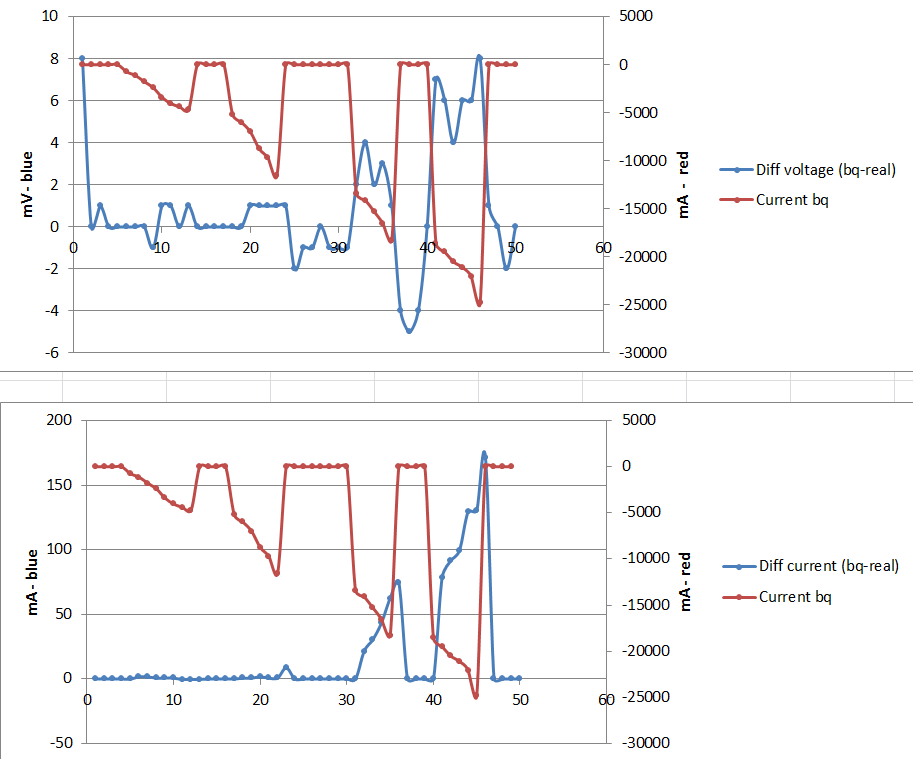
I use the bq20z65 with a 5mOhm as sense resistor. I'm currently testing the voltage and the current read from the bq20z65 and the real true one. So I've regularly decreased the load to increase the current with a few break during the process.
The graphs below shows the result: (the right axe is for the red curve, the left one for the blue curve)
We see that for the 1st graph the difference between the real voltage and the read one increases with the current (due to the heat I think). Is that normal ? At rest (no current) the difference is lower which is good but, is this difference low enough ?
On the second graph, the difference of current increase with the current as soon as we go higher than 12A, I think it's due to the heat. Do you think it will works like that ? The bq20z65 will integrate a wrong current ?
(For my use the bq20z65 will deliver about 14A with sometimes 35A during 10sec.)
It would be preferable to compare apples to apples. It will make for easier interpretation of the data if you had converted the voltage to current and then compare the real values to the what's measured by the bq device.
Measurement drifts of the coulomb counter is expected with increased temperature but ought not to be significant enough due to the precision of the ADCs used to affect SOC measurements. please refer to the data sheet of the device for questions on the specs on the temperature drift of the couloumb counter.
If you will be measuring up to 35 A, I suggest you configure your data flash currents according to the slide from one of our deep dives which I attached for you in an earlier post.
Yeah I will measure up to 40A in fact. So I just have to configure my data flash in such a way, because below ~ -32750mA the current is taken as positive due to the current 2 bytes register... nice...
I've read the slide you mentioned. So I choose to tell the bq20z65 2A instead of the real 4A passing through the sense resistor.
I will make the necessary changes for the current protection.
But the bq20z65 will then integrate a false current, this will lead to a State of charge of 50% (from 100% and if the battery is discharged continuously) instead of 0%? isn't ? And, what does it happen if the battery is discharged then at rest (minimum 35mn) then discharged again. The SOC will be seen as 50%=0% for the discharging, 0%=0% for the rest time and 50%=0% for the discharging again ?
Hi Alex, The State of Charge will still be 0-100%, however the reported capacity as well as the currents that's reported will be halved. This can easily be accounted for in your host controller if you have one.
But then do I have to do a new chemical selection and a learning cycle again after the calibration ? And do you see any problem with the interaction with the smart charger bq24735 ?
I've saved the data during the discharge of the battery (6250mAh) for the chemical selection. I did previously a calibration of 2A while 4A were passing through the sense resistor because I need to go higher thant 32.7A.
I do the chemical selection with the mathcad file of TI "chemselect_cont_rev35_mcd11.xmcd". Normally it works but now it doesn't work... :( and I'm very busy with the time...
Here is the file with the time elapsed, temperature, voltage, and current (which is half current exactly)
If you have already identified the chem id of your cell, you do not need to redo the test to identify chem id. All you need do now is select your chem id and then run a learning cycle with your new settings.
if you do not have the chem id yet, the data needs to be logged every second and not every 10 secs as you currently have it in the excel sheet.
Thanks for your answer. So I did the chemical selection with the real current and I obtained the chemical ID (1112). Then I have calibrated with half the current and I'm now doing learning cycle.
Apart from that, do you know when is triggered the Alert PIN on the bq20z65 ?