This thread has been locked.

If you have a related question, please click the "Ask a related question" button in the top right corner. The newly created question will be automatically linked to this question.

Cascading LM317 regulators for LED Backlight

Other Parts Discussed in Thread: LM317

Hello,

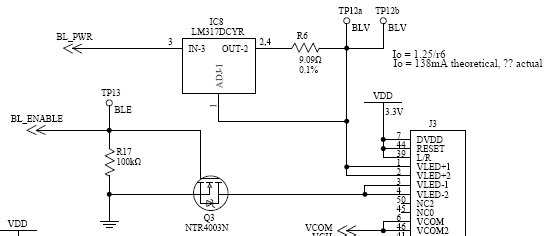
   I am looking at an old circuit that was used to power an LED backlight for a display. The concept is to use one LM317 as a voltage regulator to regulate 24V to 11.8V. After that the voltage is fed into another LM317 acting as a current regulator to feed 200mA at 9.3V to the backlight circuit. After investigating the current draw from the display, the current is very low, closer to 80mA. Should we be using a different circuit to drive the backlight, and if this circuit is ok to use, what should I be looking at as the cause for the low current output.

  • Without knowing details about the LED's, it's hard to say.

    I presume that Q3 is either ON or OFF, that there is no PWM'ing via the BL_ENABLE signal.

    It's quite possible that the circuit is working exactly as originally intended. Possibly, IC8 is there to limit the peak current, not to provide ongoing constant current.

    The 9.3V is most likely the voltage drop (i.e. insertion loss) across the circuit. At least 1.2V from the NPN darlington, plus no more than 1.25V across the sense resistor. So 11.8V - 2.5V = 9.3V sounds about right.

    It's possible that 80mA current draw with 9.3V applied to the LEDs might be the proper behavior for the LEDs ... OR ... something on the LED side has caused an increase in the compliance voltage. Possibly some extra series resistance, some shift in the LED Vf (this one seems unlikely), or ??

    You would need to find the electrical details on the LED's to determine the voltage (Vf) vs current (If) behavior and requirements.

  • Thank you for your response. After you comment I realize that I left out a bunch of information which would help out here.

    9.3V at 200mA is given in the datasheet for the LED Backlight

    Q3 is just an on/off switch, no PWM.

    I have connected the LED backlight to a calibrated voltage source to see what it should draw, and at 9.3V the LEDs were drawing 205mA. I did notice that the actual voltage at the output of my current driver circuit above the voltage is 9.0V, but even that was drawing about 170mA when connected to the power supply.

    It seems to me like the LEDs want more current from this circuit, but they are not getting what they need. I did notice that R69 might be an extra component. I don't see this in application circuits for using the LM317 as a voltage regulator.

    I think my next step is to try shorting R69, connected the negative of the circuit directly to ground instead of through Q3, and anything else anybody can suggest to see if I can find what is limiting the current.

  • For LEDs typically the current through them is well controlled, and the voltage is whatever it is. So if you reversed your test condition and FORCED a constant 200mA you should end up with about 9V across the LEDs. Change the current by +/- 20mA and see how much the voltage changes. The resulting voltage will change with the temperature of the LEDs, and the amount of change would depend on how the LED array was put together (series/parallel).

    R69 would be there to reduce thermal dissipation in the voltage regulator. In this case it's not going to do too much.

    My two cents ...

    First the current limit circuit, IC8, is now set to limit the current at Vref / R6 = 1.25V / 9.09 = 137mA. You will never get to 200mA. So R6 needs to be changed to 6.25 ohms get 200mA.

    Then increase the voltage regulator IC13 output voltage to be at least 4.25V above the LED Vf @ If=220mA. That puts the minimum Vin-Vout of 3V across IC13 plus 1.25V across the sense resistor, plus gives some headroom for changes in Vf.