This thread has been locked.

If you have a related question, please click the "Ask a related question" button in the top right corner. The newly created question will be automatically linked to this question.

BQ24100 Charger questions

Other Parts Discussed in Thread: BQ24100, BQ24104, BQ24103

. I am looking at incorporating the bq24100 switchmode Li-Ion charger for the “base” charger to charge our new project’s removable battery. I have gone through the datasheet, calculated out all my component values. On page 7 of the spec sheet in Figure 1 there is a zener diode(it is actually a dual channel) connected to the output before the inductor. There is no mention of it , to my knowledge, in the data except for a note in figure 2 that states the diode is not required for bq24103 and bq24104. I would like to know what it is for and what parameters it must meet. I have ordered the evaluation module for the bq24100 and looked at the schematic for that as well as the bill of materials and did not see it used at all. The only thing that I can think of is ESD protection since that pin will interface with “outside” world.  


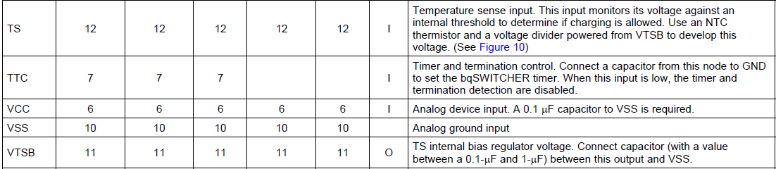
Also, I do not plan on using the temperature sense feature and the spec states to connect the pin to a constant voltage if not being used. Can VTSB be incorporated to accomplish this condition?

  • Hello Sevrum,

    The diode between output and ground is explained a little bit better on Pg.6 of the datasheet stating the purpose of the TVS diode is to protect the output pin from abnormal voltages by clamping it when necessary.

    So while it might not be listed as needed for some of the devices they could benefit from having the additional protection especially if the voltage limits of the device are expected to be tested.

    To answer your second question. Yes, VTSB can be used to generate this bias voltage. This use is discussed on Pg. 6 of the datasheet for biasing the NTC. If the temperature sense feature is not desired you would simply design a resistive divider to ensure the TS pin senses the correct voltage discussed on Fig. 10 in the datasheet.