This thread has been locked.

If you have a related question, please click the "Ask a related question" button in the top right corner. The newly created question will be automatically linked to this question.

I can not operate at higher currents the LM2678

Other Parts Discussed in Thread: LM2678

Hello Frinds


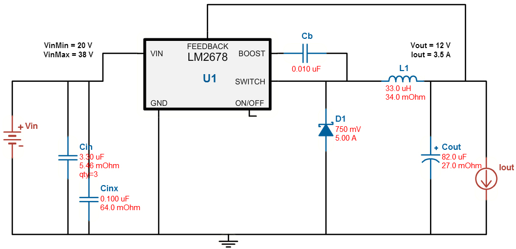
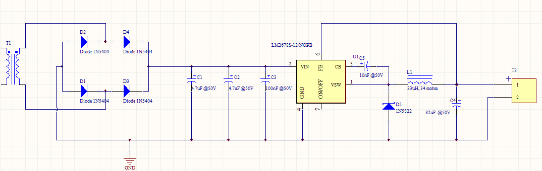
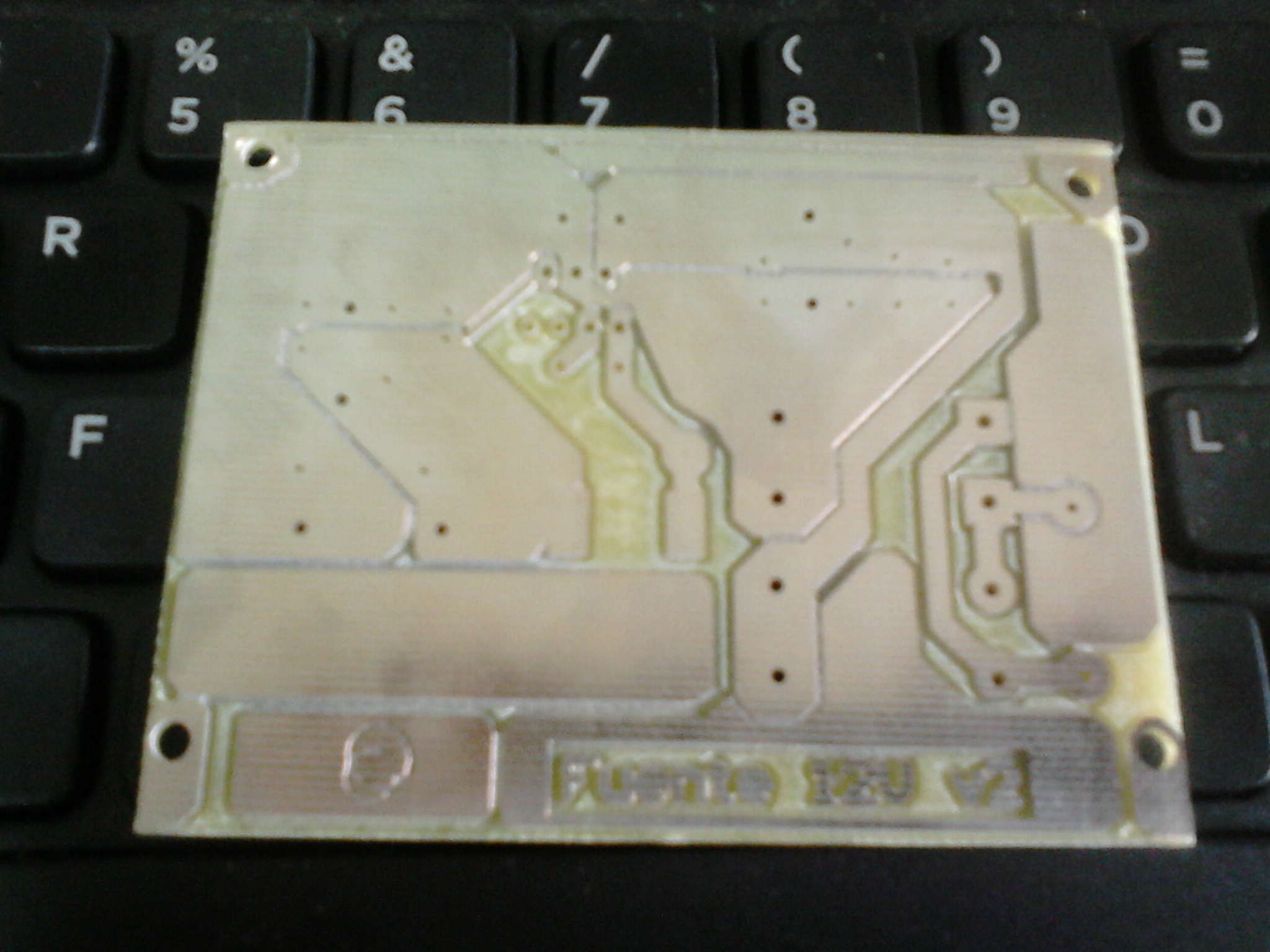
I decided to build a 12V @ 3.5A power supply with a LM2678-12 ( previously I made a 17V @ 0.6A power suppy with LM2595-ADJ and works pretty well). I inspired in such 17V power supply PCB to make the new one.

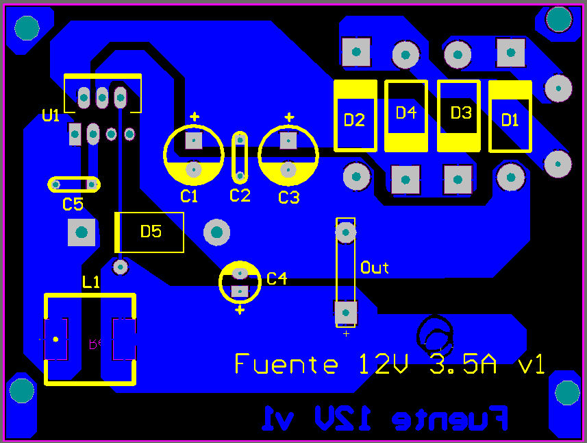
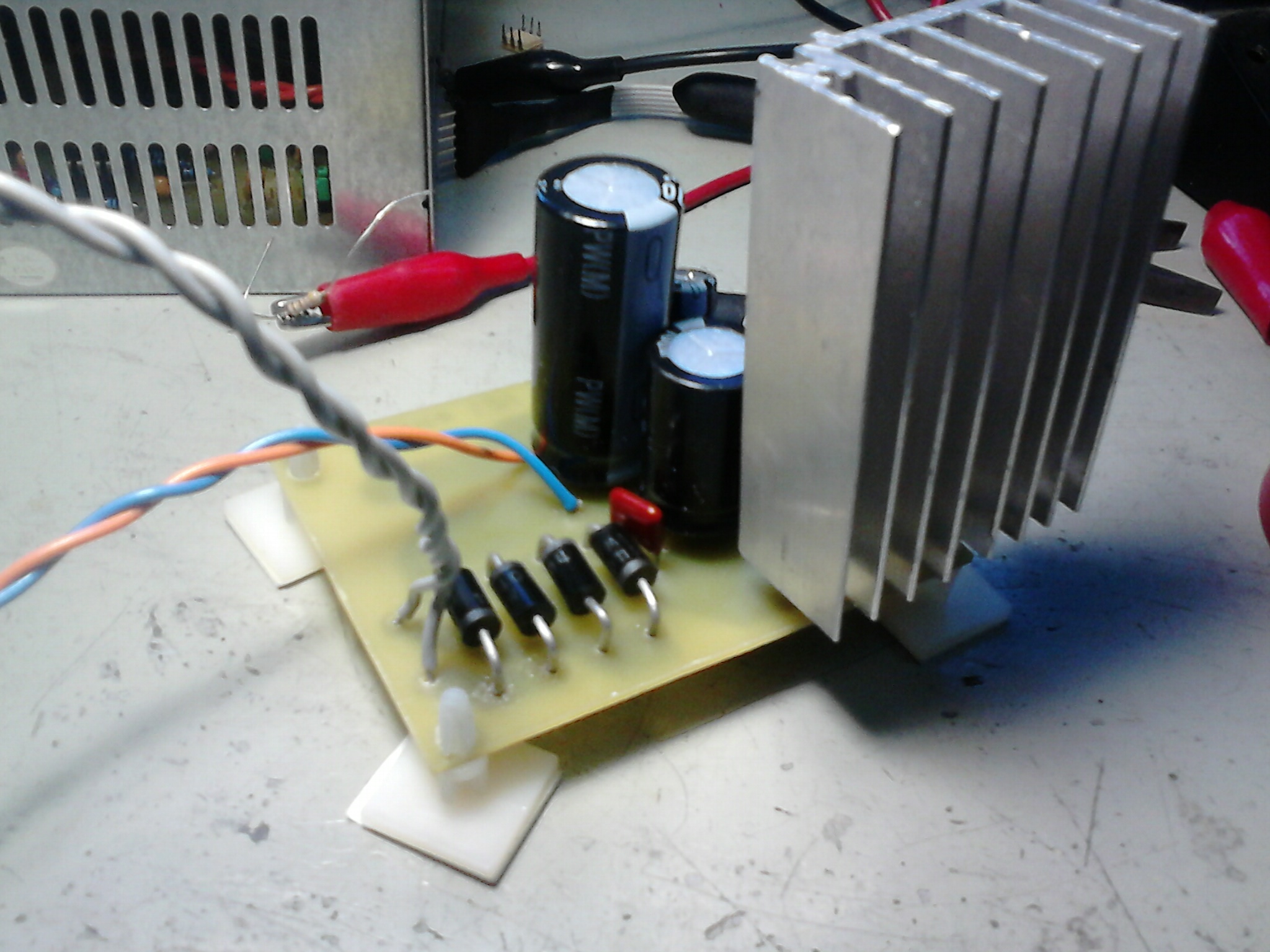
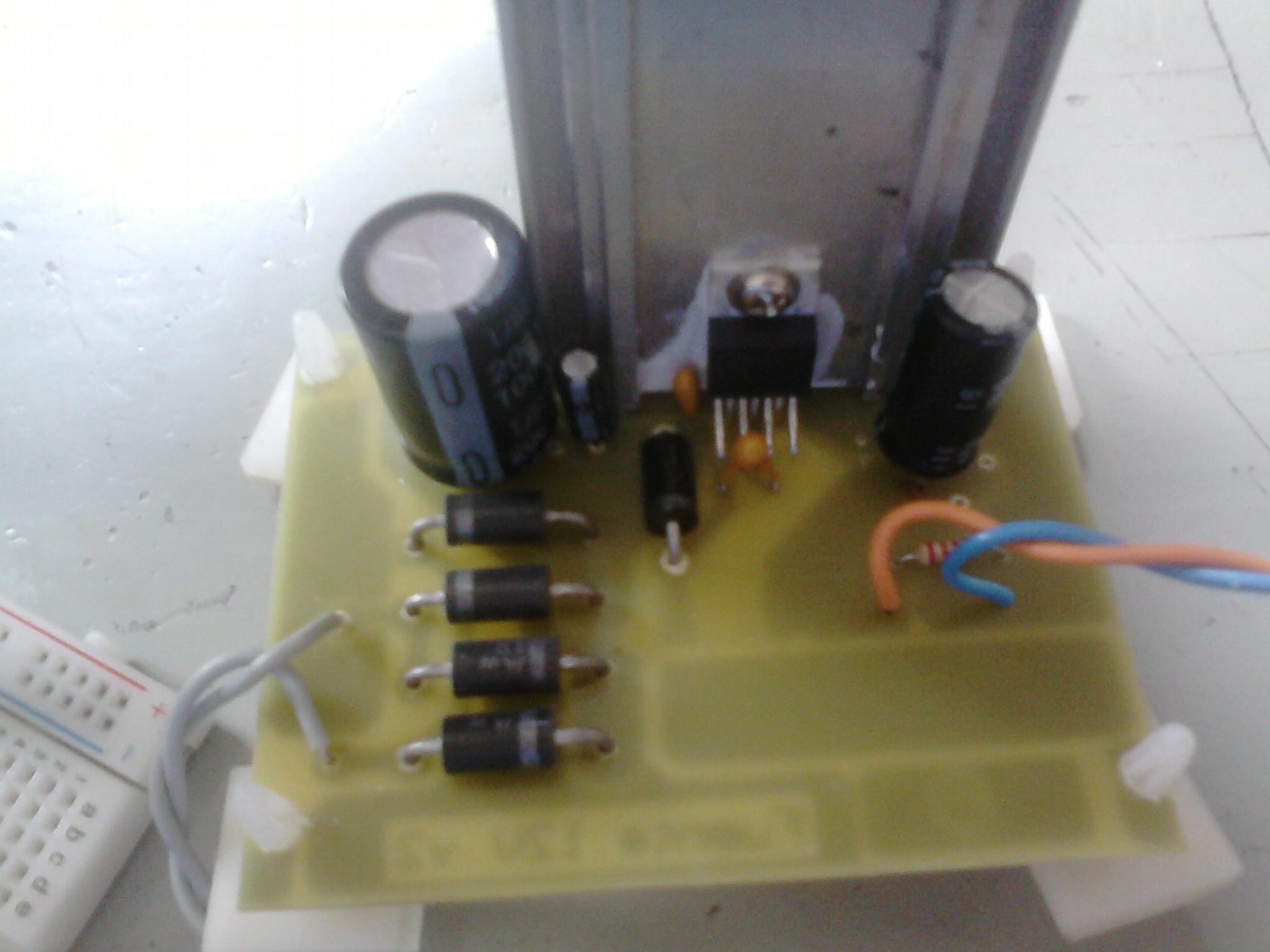
One general constraint was to use through hole components while were possible.

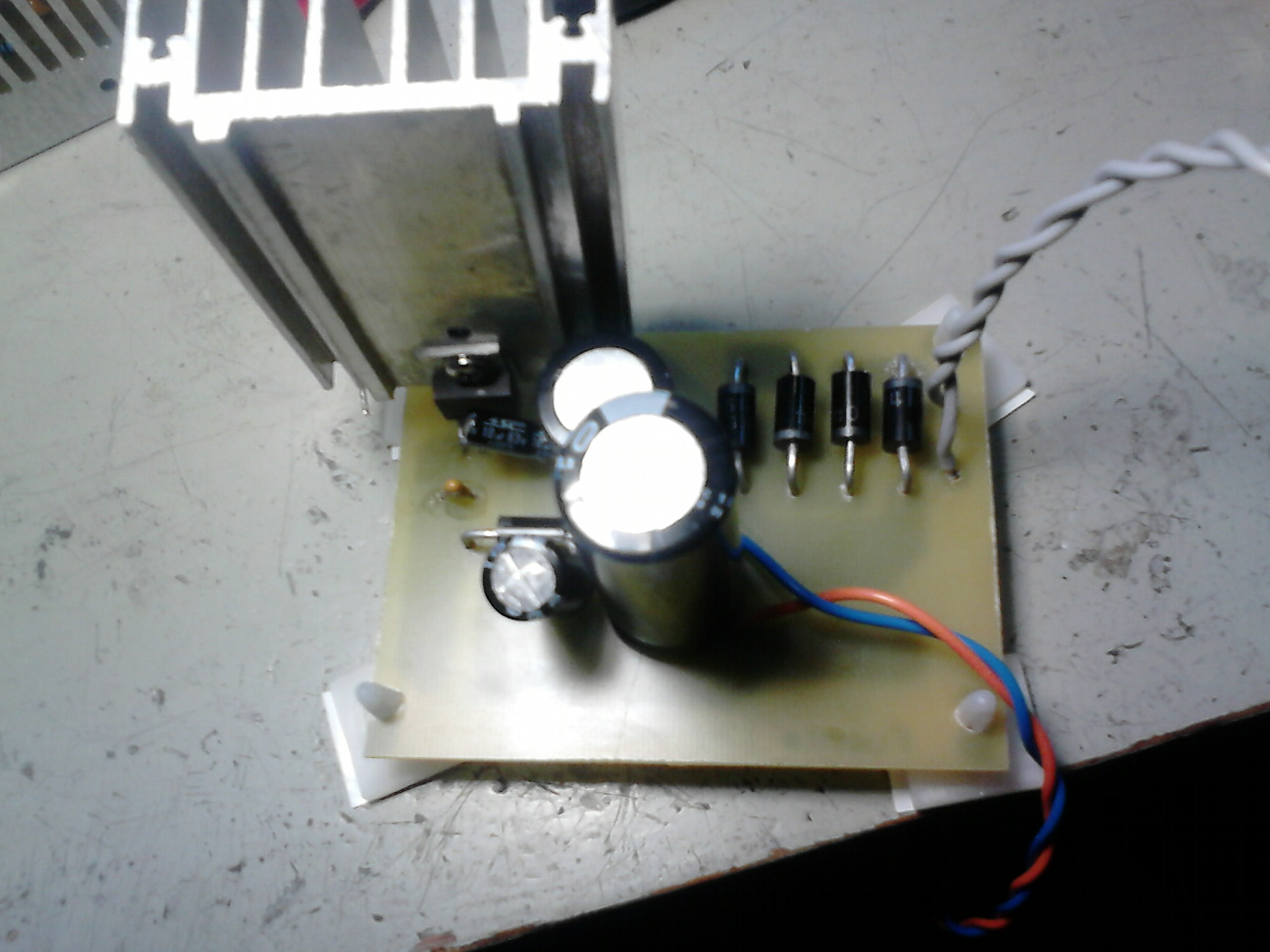
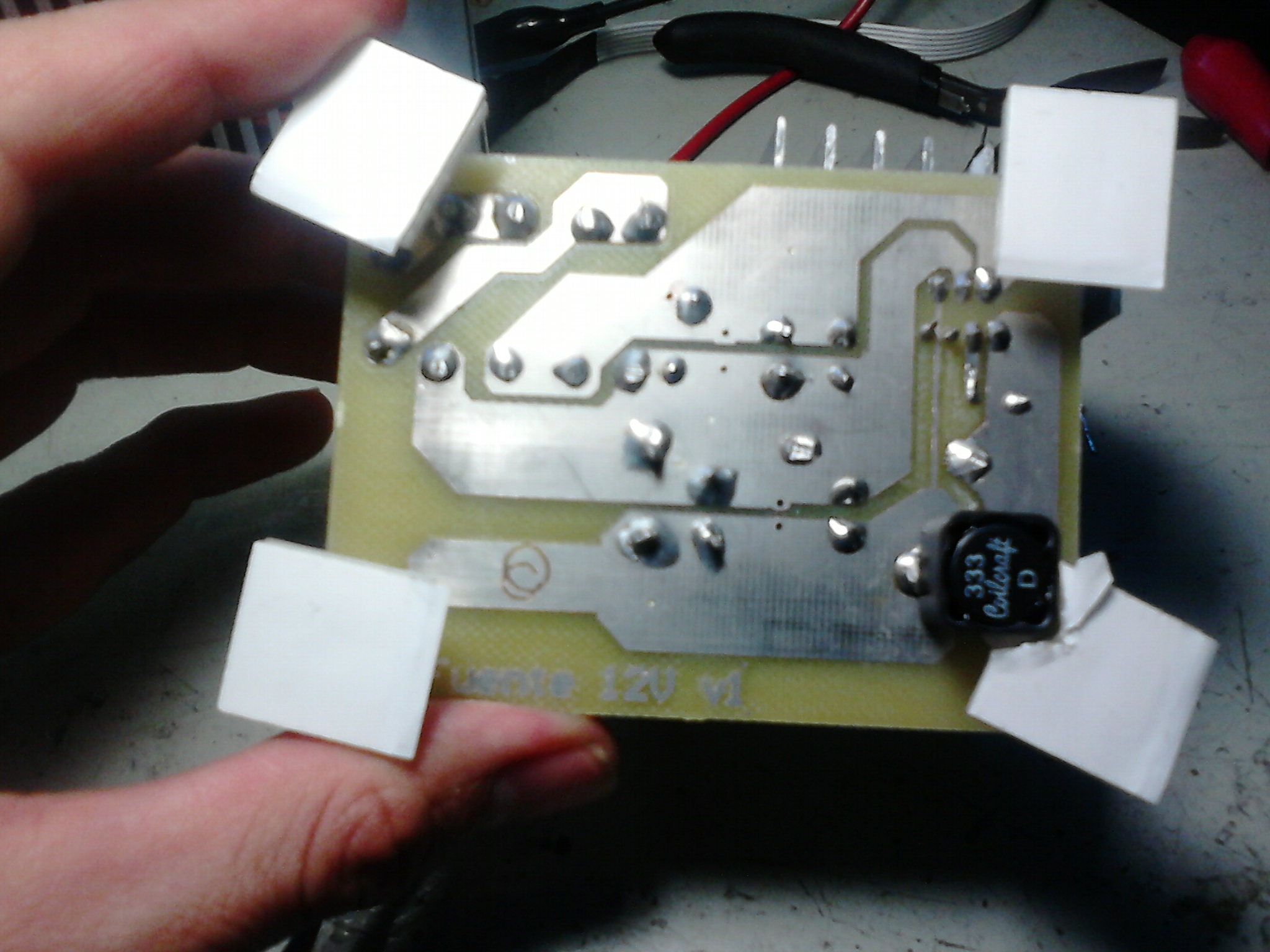
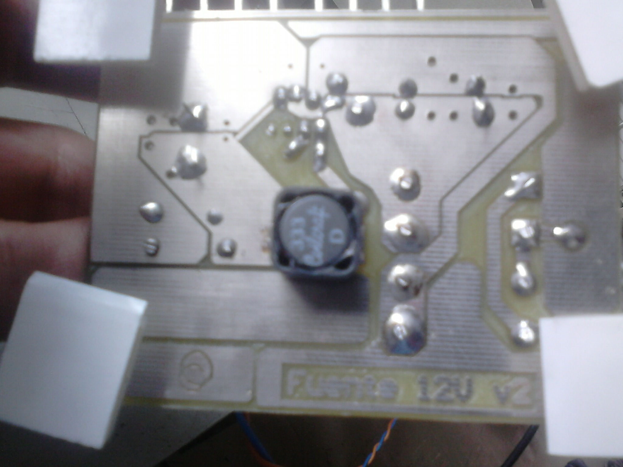
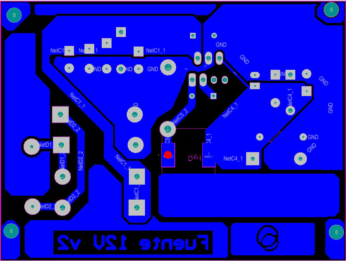
Finally I built the PCB of the 12V power supply with the aproximation of Ti.com/Webench then made the PCB with some extra holes in case i must change some kind of capacitors (input/output capacitors).

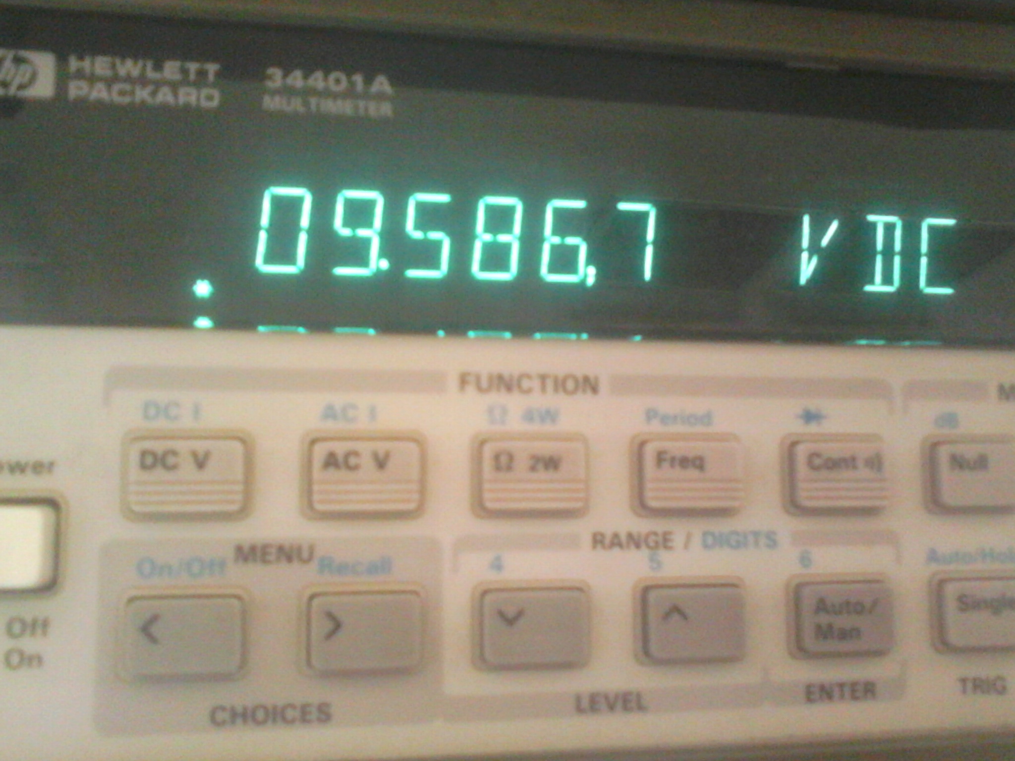
When i finished it, I should put a 2.2kohm like light load because without load the voltage output began to rise far of 12V.

Then in progressive way i began to rise te load until 1.5 A and works well, but with higher loads simply the LM2678 dies.

I tried with differents values of input/ouputs capacitors, also i tried put them closer of the input. the LM2678 was burn without heat.

i changed and gradually the capacitors values until higher values reach 1000uF. Also put it them diferents kinds of capacitors (ceramic,plastic, etc)

any suggestions?

  • Hello,

    You might be seeing some really large spikes on Vin. Have you probed the Vin node? Try adding a couple of ceramic 0.1uF caps right between the Vin and Ground pins on the back side. Having a through hole layout for switching regulators is not advisable. You could be seeing some large noise coupling in to your circuit.

    Regards,
    Akshay

  • Hello Akshay Mehta. I appreciate your interest.

    I did´t see anything on Vin even when i probed the Vin node, instead the only thing i saw was a little transitory wave on Vout (i must pay attention the next time).

    curiously when i added some capacitors like you told me was when more LM2678 blowed out.
    And yes, i knows the dificulties that through holes represents, but i wanna try this because is a interesting challenge also here is easier to get through holes parts.

    Is there any other suggestions?

    Regards

  • I am quite surprised that you see increased failures when you add the bypass cap. Was it a ceramic cap and placed very close to the input pin and ground? If the device blows up without heat, then there is some sustained voltage above it's maximum being observed someplace. Have you made sure that your scope bandwidth is wide open so as to allow you to see any noise on the SW pin and VIN pin?

    Regards,
    Akshay

  • Hello Friend
    its me again, after of not little while finally i could continued with my buck power supply.
    As you said , i put ceramic cap very close to the input and the ground. The load is 5 ohms to obtain 2.4A.
    And Again, i did not see a improvement.

    I made a new PCB, following a guideline to work better in high frecuencies. Such this was a reduce ground loops and in certain way separate the interference of the input versus output. Also to put the components close in the case if they shoud need it.

  • Hello,

    So you are still not able to get full load out of your design? Have you tried to use a demo board/EVM that was built for LM2678? They are available on the web.

    Regards,
    Akshay