This thread has been locked.

If you have a related question, please click the "Ask a related question" button in the top right corner. The newly created question will be automatically linked to this question.

BQ2002D CC Pin connection

Other Parts Discussed in Thread: LM317, BQ2002, LM1117, LM117

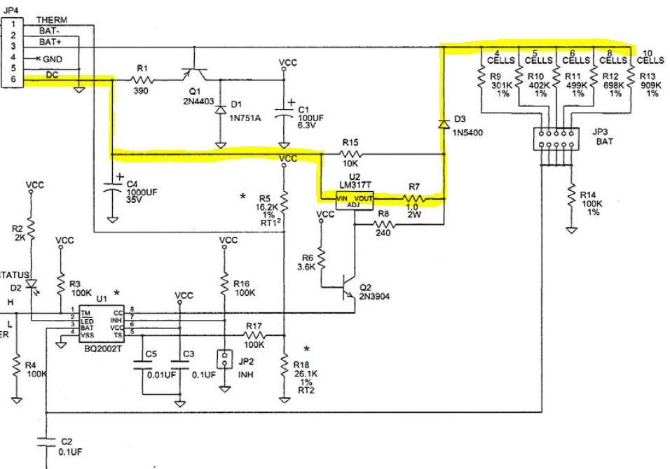
The only schematic I could find is the schematic that is shown in the http://www.ti.com/lit/ug/sluu007b/sluu007b.pdf pdf file.  My question is what is the purpose of Q2.  It seems that all the current will go through the chip anyway and the transistor is on continuously.  Do you have another reference document that shows the proper connection for this chip.

If the current source is limited to 100ma do I need to monitor the temperature of the two 1000 mah AAA batteries?

Thanks

Mark

  • Hello Mark,

    The charging current is passing as follows through the system.

    The purpose of the Q2 is to turn the regulator LM317 on and off by being High-Z or open sink.

    Here is a post on a different forum that showing a different users approach to using this part that clears up the role that Q2 plays.

    http://www.eevblog.com/forum/beginners/battery-charger/

    Whether temperature monitoring is needed or not is a function of many things between charging current, ambient temperature, manufacture specs, and others. With a charging current that low if the ambient temperature is also low you might be able to get away without monitoring the cell temperature.

  • Ryan Thanks for your answer.

    I have a BQ2002 in a board using a LM1117.  The voltage drop across the device and diode is not allowing the voltage to rise above 3.1 so the cells only get 1.5 volts per cell at full charge.

    I have seen a device using the BQ2002 and it is using a ldo regulator charging at 250 ma.  I cannot identify the regulator it is a SOT23 5 terminal device with a 3.0 ohm resister as the current limit.  The marking on the device is A10B.

    Do you know of an .3 LDO regulator that I can substitute for the LM1117.  Thanks 

    Mark

  • Hello Mark,

    I am going to need a little bit more information about your system to be able to help you out.

    What is the flow of power? What is the input voltage and then what is the arrangement of the devices (Input, bq2002, lm1117, battery, load)?

    What package are you looking for in the LDO? Are you trying to move to SOT23-5 or are you wanting to drop into the same pad that you are using for the LM1117? If you are wanting that then the question is what is the package of the LM1117?

    What drew you to the LM1117? Is there a feature that attracted you to it so that the same feature can be looked for in a replacement?
  • Hello Ryan

    What is the flow of power? What is the input voltage and then what is the arrangement of the devices (Input, bq2002, lm1117, battery, load)? 


    As you outlined in the first response.  The flow is the yellow line.  The input voltage is USB power 5 volts.  I set the current to 250ma  which is C/4 for two 1000ma AAA batteries.  I currently have the full charge set to 3.0 volts with a 180K and 350 K to ground going to the bat pin 3.  The voltage does not get high enough to stop the charge.

    What package are you looking for in the LDO? Are you trying to move to SOT23-5 or are you wanting to drop into the same pad that you are using for the LM1117? If you are wanting that then the question is what is the package of the LM1117?

    Any LDO I will do I am only going to charge at 250ma and any package.

    What drew you to the LM1117? Is there a feature that attracted you to it so that the same feature can be looked for in a replacement

    The application note showed the lm117 and the 1117 acts the same but it still drops too much voltage.  I know it can be done because I have a device charging at 250ma with the usb.

    Thanks for your help

    Mark

  • Hello Mark,

    You might be running out of voltage overhead. The forward dropout voltage of the LDO combined with the current setting of R7 might be causing this issue.

    You could look into any of these devices:
    www.ti.com/.../single-channel-ldo-products.page;1&p1498=Catalog&o4=ACTIVE&p985typ=30;500&p182=Adjustable%20Output&p634min=0.8;5&p634max=5;34&p238max=5;36&columnOrderString=o1,o4,p182,p451max,p238min,p238max,p1154,p634min,p634max,p1342,p1498,p1192,p2954,p1811,p1130,p985typ
  • The key is to find a LDO that has a lower dropout voltage. The goal will be select a LDO that has a Vdo of less than 1000mV