Hello,
I am using a BQ25570 (Figure 1), and I have a problem with VBAT_OK digital signal.
I set VBAT_OK at the following thresholds :
VBAT_OK_HYST = 3.0V
VBAT_OK_PROG = 2.1V
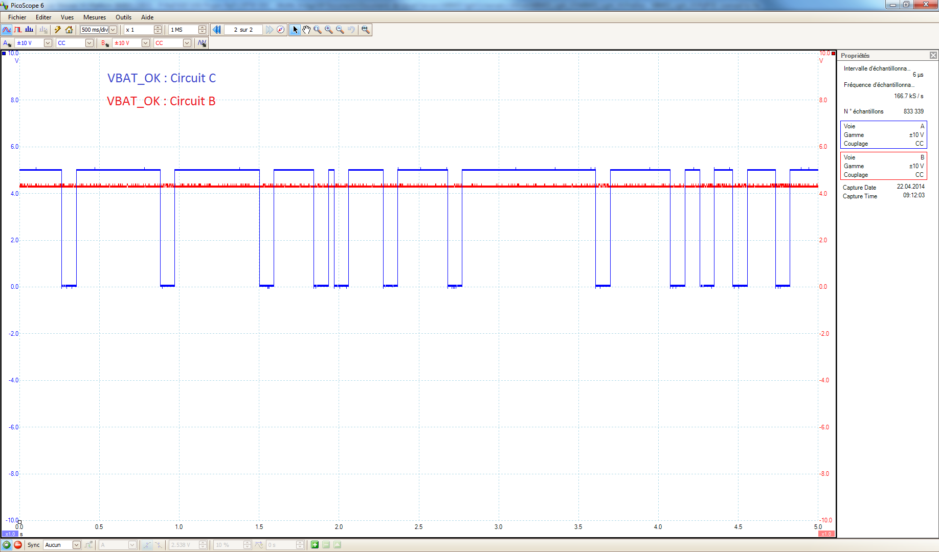
VBAT_OK, is toggled correctly at the threshold points, but when the VSTOR reach the maximum VBAT_OV (Set to 5.0V). VBAT_OK signal start to have a strange behaviour, in fact, VBAT_OK toggles randomly (Oscillogram 1). It appends only when solar cells are lighted, this mean only when the system is charging.
On the oscillogram, VBAT is not shown but VBAT is stable,but not VSTOR. We can see, that VSTOR signal peak to 5.4V.
BQ25570's datasheet explains VBAT_OK digital signal operation, maybe I miss something, but I didn't expect this kind of behavior.
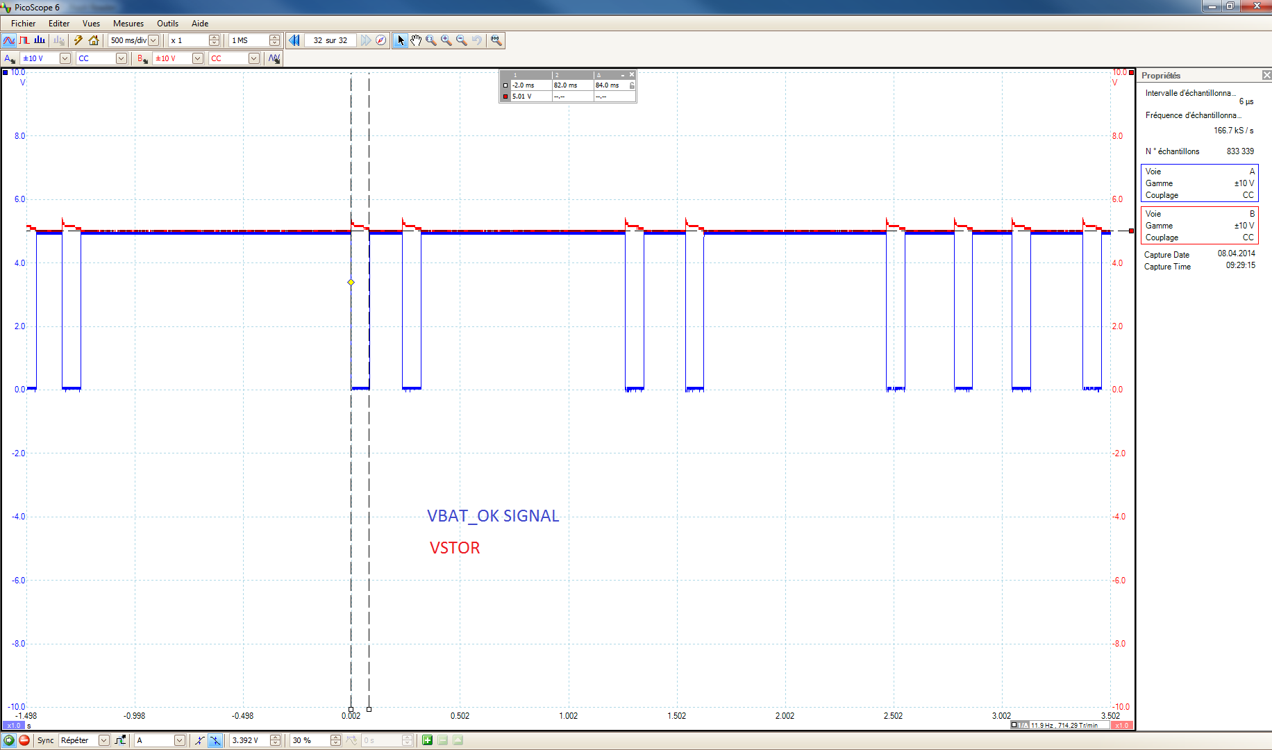
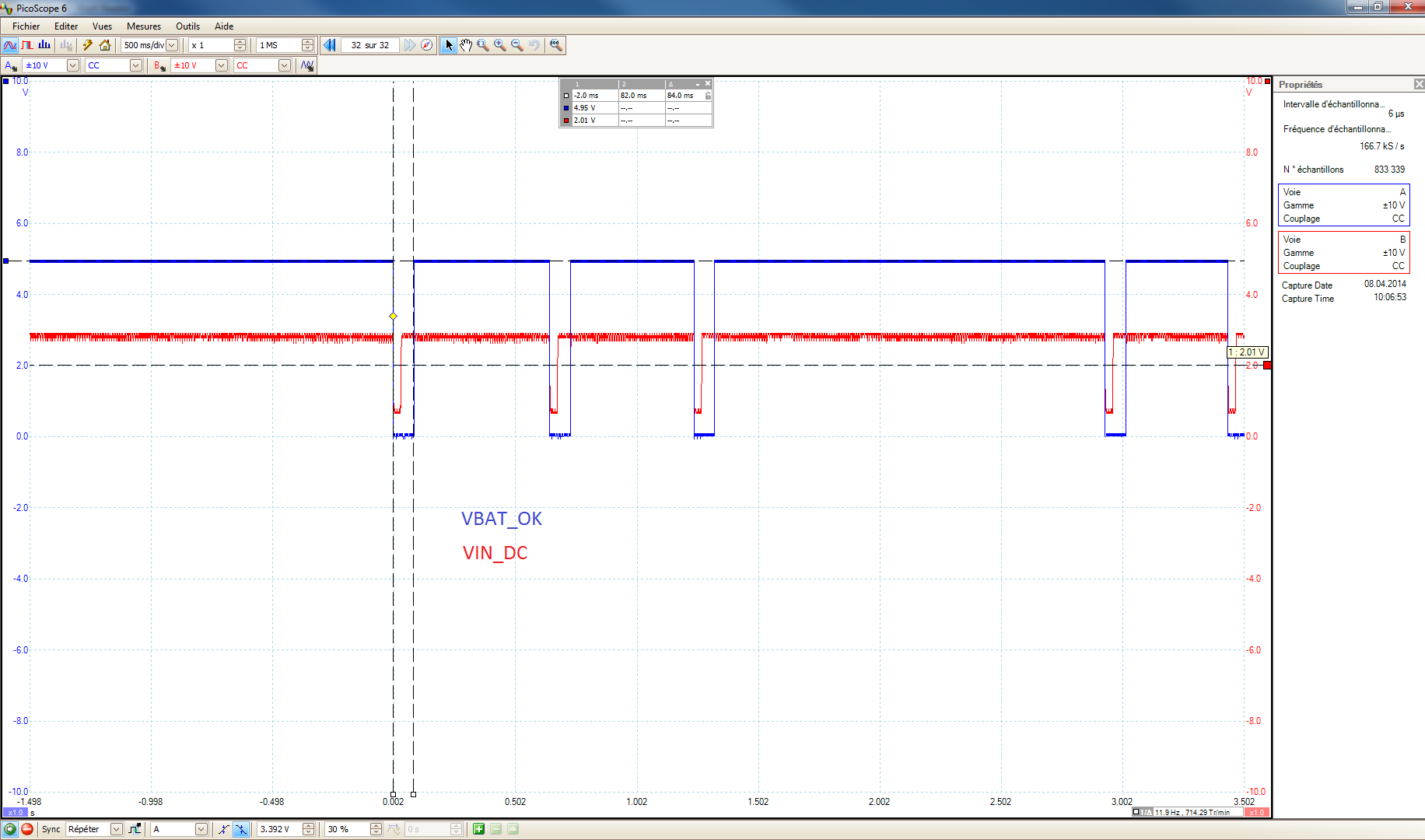
Datasheet mention that BQ25570 does a "short-circuit" on VIN_DC in case if VIN_DC > VSTOR and VSTOR == VBAT_OV. (Oscillogram 2) show VBAT_OK and VIN_DC. I think is not what append in my case, because VIN_DC is never higher than VIN_DC.
It may be the threshold which does not work properly, so I have done a measurement (Oscillogram 3) : Show VBAT_OK and VRDIV (PIN 8). I don't know why VRDIV signal behave different when VBAT_OK toggle low.
Any suggestions ?
Best regards.
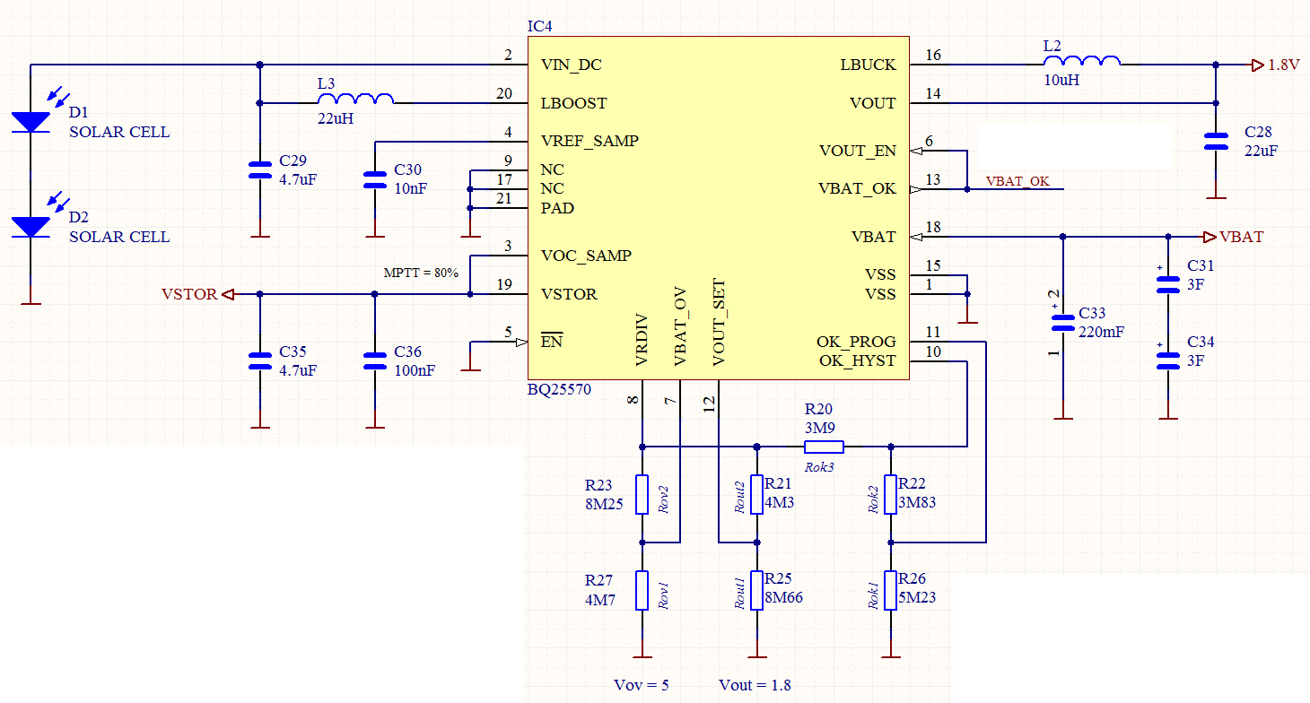
Figure 1
Oscillogram 1
Oscillogram 2
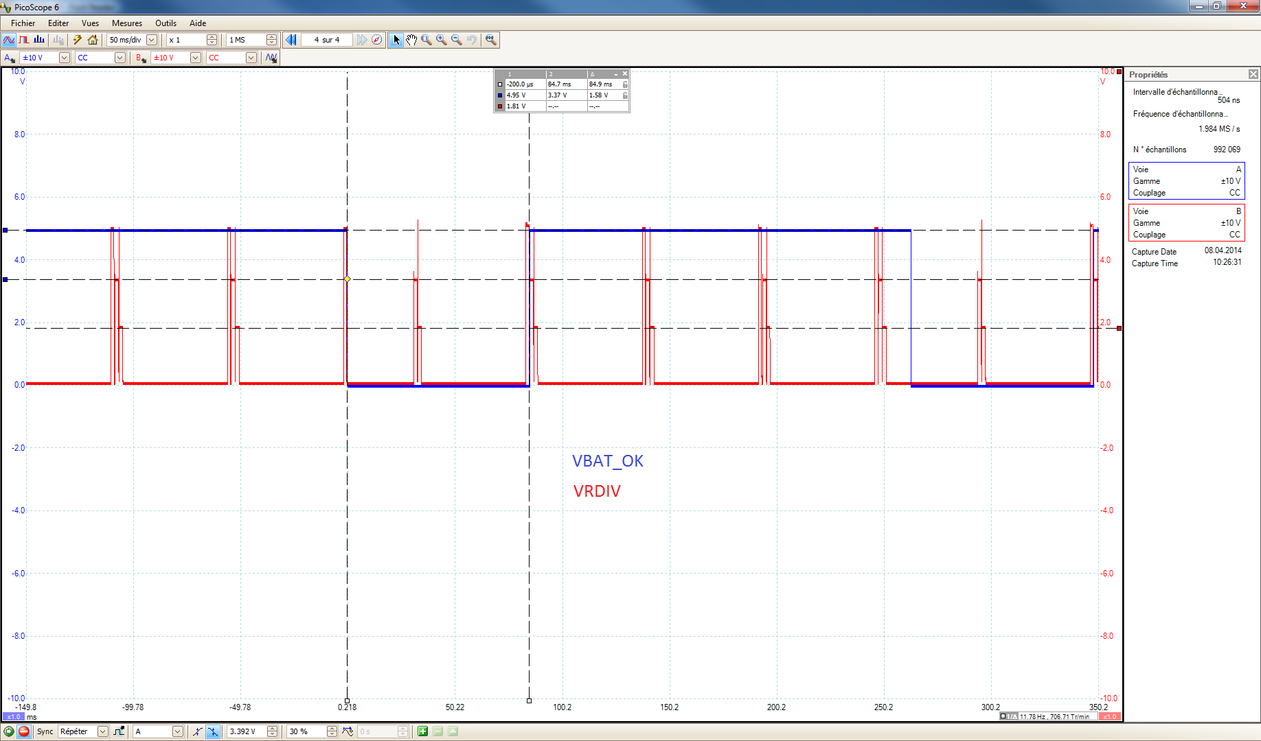
Oscillogram 3