


I have built two four-channel, master-slave, test circuits around the LM3445 Triac-Dimmable Offline LED Driver.
The first version works pretty well, although the channels do not have equal power outputs.
Both versions are mostly surface-mount and use a common rectifier bridge to supply the master and the three slaves. This first version was hand-built.
I can supply a schematic if you are interested.
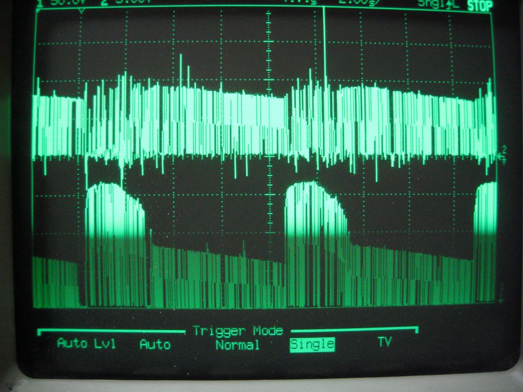
The operation of this version is shown in the first attached photo, labeled Normal Operation. The top trace is the drive signal to the gate of the switching MOSFET. The bottom trace is the drain voltage waveform for the MOSFET. You can see that the operation is continuous as the dimmer turns on and off in each line cycle.
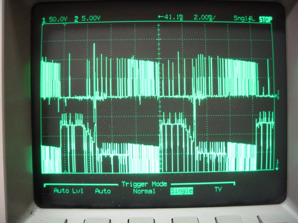
The second, nearly identical version I built does not work well at all. It exhibits a strange behavior that prohibits it from reaching full power. I would have enclosed a scope photo to show this behavior, but T.I. e2e forum only allows one enclosure. I can send you the second photo if you are interested. Anyway, when the dimmer is dialed up, the gate-drive signal becomes erratic and intermittent, and the drain voltage follows suit. The result is no significant power output. This board was built by a professional PCB house.
The schematic for these two versions is identical. The layouts are nearly identical. Yet, buried somewhere in the physical board is a reason why the gate-drive voltage takes a holiday as the buck voltage rises with the dimmer. The ramp voltage on the Coff capacitor ceases as well. I cannot figure out the cause of this very different behavior for two nearly-identical circuits. It seems that the constant-off-time has been arbitrarily extended so that very few "on" cycles actually occur. I keep looking back and forth from the working version to the not-so-working version, trying to come up with something that I can do to flush out the problem.
I cannot settle on a final LM3445 design for production until I understand how to solve this problem and keep it from recurring.
Have you any experience with a four-channel version using the LM3445?
Thanks,
Benny Smith
