This thread has been locked.

If you have a related question, please click the "Ask a related question" button in the top right corner. The newly created question will be automatically linked to this question.

BQ27200 - I2C Incremental Read - Only first byte is sent

Other Parts Discussed in Thread: BQ27200, BQ27000

I am working on a prototype of a rechargeable battery pack for a commercially produced Arduino shield and I am trying to test the communications with the BQ27200 Gas Gauge IC that we have included in the design. I have tried using the "Wire" library (offically supported by Arduino) and an alternative I2C library with better implementation of the repeated start condition.

My test program is as follows:

#include <Wire.h>

byte data[6];

unsigned int Temperature;
byte Add;

void setup()
{
Serial.begin(9600);
Wire.begin();
}

void loop()
{ 
Serial.println("Beginning I2C Test");
Serial.println("Reading Temperature...");
Wire.beginTransmission(0x55);
Wire.write(byte(0x06));
Wire.endTransmission();
Wire.requestFrom(0x55,6);
int i = 0;
while (Wire.available())
{
data[i++] = Wire.read();
}
Wire.endTransmission();
while (i>0)
{
Serial.println(data[--i],BIN);
}
Serial.print("\n\n");
delay(2700);
}

The output is (Memory address top byte 0x0B, bottom: 0x06): 


Beginning I2C Test
Reading Temperature...
11111111
11111111
11111111
11111111
11111111
11010111

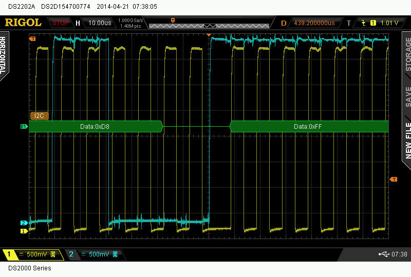
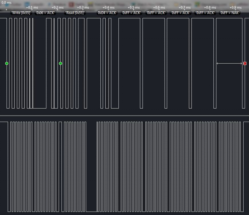
It is a little confusing looking at this because it is listed in reverse, but it is printed in the format of the memory map in the datasheet. These values are read in order from the bottom (B11010111) to the top. The first byte read is correct, but the rest are obviously not. My interpretation is that the bq27200 seems to be stopping the transmission after the first byte is sent. Perhaps it is interpreting a STOP instead of an ACK? Below is a capture of this moment in the communications (the end of the first byte read).  Both libraries resulted in the exact same waveform. Any help would be appreciated.

Thanks, Aaron

  • Here is the output from our Saleae logic analyzer. The protocol appears to be correct. Is my request for 6 bytes inadequate? Did I miss some communication caveat in the datasheet?

  • I don't have much personal experience with the bq27000/bq27200 gauges at the moment, but I will try my best to answer your questions.

    So far I don't see anything that stands out to me, but one thing I see in Saleae Logic is the address field; I'm not sure if it's using the 7-bit address notation or the default 8-bit address + read/write. What analyzer settings are you using for it? Also, could you attach a copy of the .logicdata files from one of your logic analyzer sessions (Options menu -> Save Session -> Settings & Data)

    I might grab a sample of the bq27200 and test it out on one of my Arduinos when I get the chance.

  • i've got some experience using the arduino wire library with the 27200, try to read each byte individually instead of 6 at once, block read of i2c does not work well.

  • found my old arduino code, here are the functions i used

    byte read27200(int deviceaddress, byte eaddress )
    {
      byte reqdata = 0xFF;
     
      Wire.beginTransmission(deviceaddress);
      Wire.write(eaddress);  
       Wire.endTransmission();
     
      Wire.requestFrom(deviceaddress,1);
     
      if (Wire.available()) reqdata = Wire.read();
     
      return reqdata;
    }

    void write27200(int deviceaddress, byte eaddress, byte data )
    {
      Wire.beginTransmission(deviceaddress);
      Wire.write(eaddress);
      Wire.write(data);
      Wire.endTransmission();
     
      delay(5);
    }

  • I am only displaying the 7-bit addresses. It is sending [Add 0:6][1 or 0] as the address byte.

    Here is a binary output from Logic. I had to zip is to make it an "allowable" format.

    0410.SaleaeLogicBinary.zip

  • I just tried reading single bytes with both the Wire library and this I2C library. I was able to read memory address 0x06, but anything els. Wire.available() would return false and there was no data. I'm really stumped. A couple days ago I had the 6-byte read program on an Arduino in the setup() (so, it ran on reboot and did not loo) and I accidentally left it plugged in over night. Through the night the program ran about 15 times (random reboots? o_0) and 3 of those times it actually read correctly. I found the output in my serial monitor the next morning. I have not been able to reproduce it.

  • so even if you read 0x06, then 0x07 etc you do not get valid data?

  • Correct. I can read 0x06 and 0x07 incrementally and 0x06 will return correctly and 0x07 will always return as 0xFF.

    Even if I read just 0x06 and then perform another read at 0x07, 0x07 is wrong. :-/

    BTW, I really appreciate the help, Everyone. :-)

  • the next step I would take is use a EV2300 and the EVSW along with a beagle i2c analyzer and look at the data frame to make sure there is nothing i'm missing. Unfortunately I dont have the time to run that experiment right now.

  • I just played with my 6 byte read program again, starting at memory positions other than 0x06, and the first byte always reads correctly while the others are 0xFF. (Starting with both even and odd addresses.)

  • yes the AVR twi doesn't support block reads well, and the i2C master library still leaves something to be desired (bit banging multi start is a crapshoot at best). If you didnt say you were developing an arduino shield my first piece of advice would have been ditch the arduino for an ARM or PIC as i have never had i2c issues with either.

  • Hmm... That's interesting. A previous iteration of our shield uses the DS2745 (Dallas/Maxim) fuel gauge and, with that, I don't have any problems performing a block read with the AVR. We decided to switch because the BQ27200 is vastly superior. 

    I don't think there is any problem in the circuit, but I'll include those details as well. There are 100ohm resistors in series with SDA and SCL. There are also 4.7k resistors pulling SDA and SCL up to 3.3V. The rest of the bq27200 is wired as per the datasheet, though the polarity of the sense resistor may be reversed. (SRN is battery negative)

  • I just realized that I sampled my last logic analysis at only 1 Mhz. 1 microsecond resolution isn't very helpful. Here is a new set of files. This contains a csv and binary of a 24 Mhz analysis.

    0310.LogicAnalysis.zip

  • I'm still curious to hear an official TI opinion on this matter.