This thread has been locked.

If you have a related question, please click the "Ask a related question" button in the top right corner. The newly created question will be automatically linked to this question.

bq24030 does not charge the battery, all the LEDs Off

Other Parts Discussed in Thread: BQ24030, BQ24031, BQ24030EVM

Hi everyone!

I have been suffering a problem for 2 months and I have still unable to fix it.

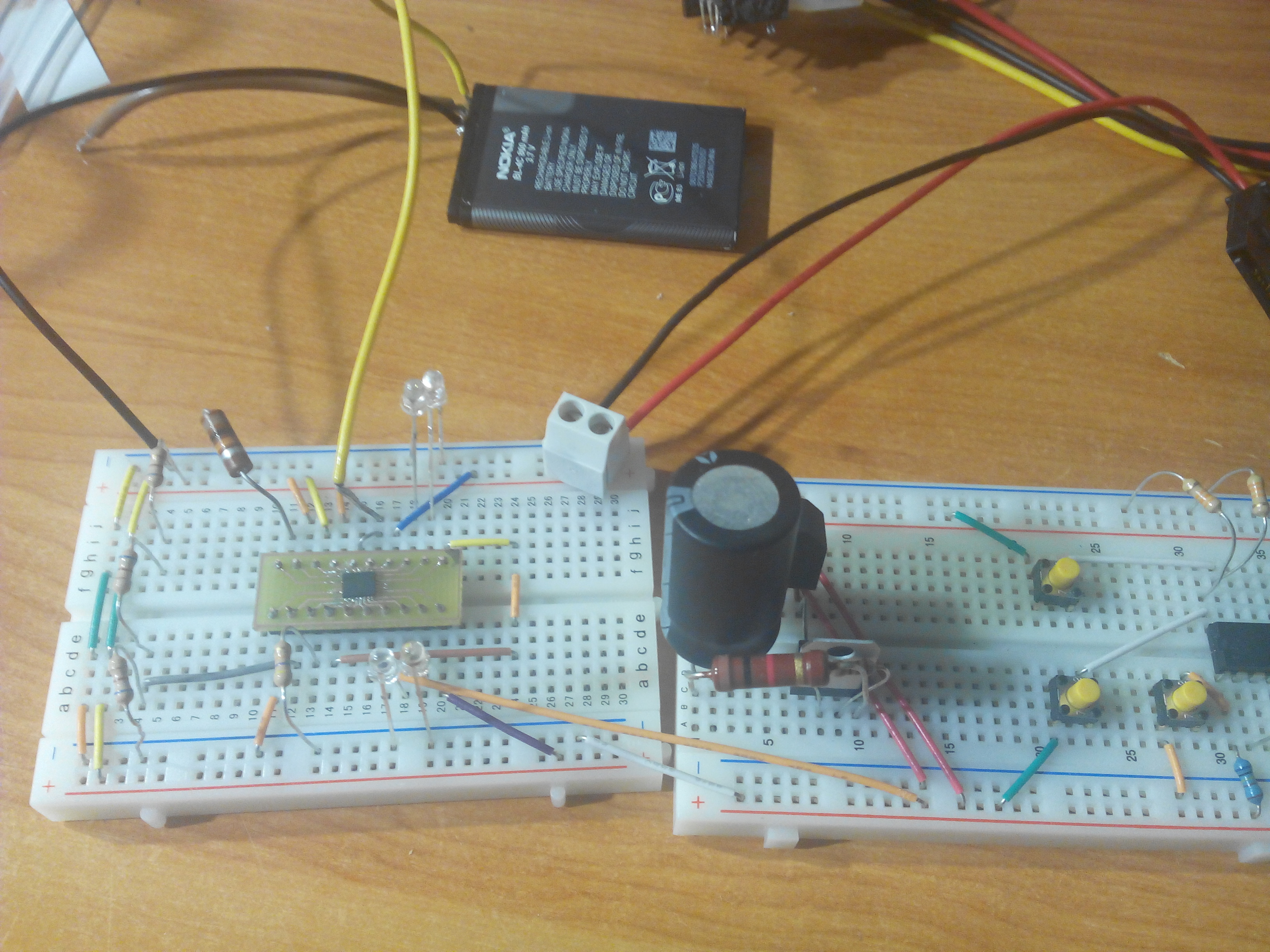
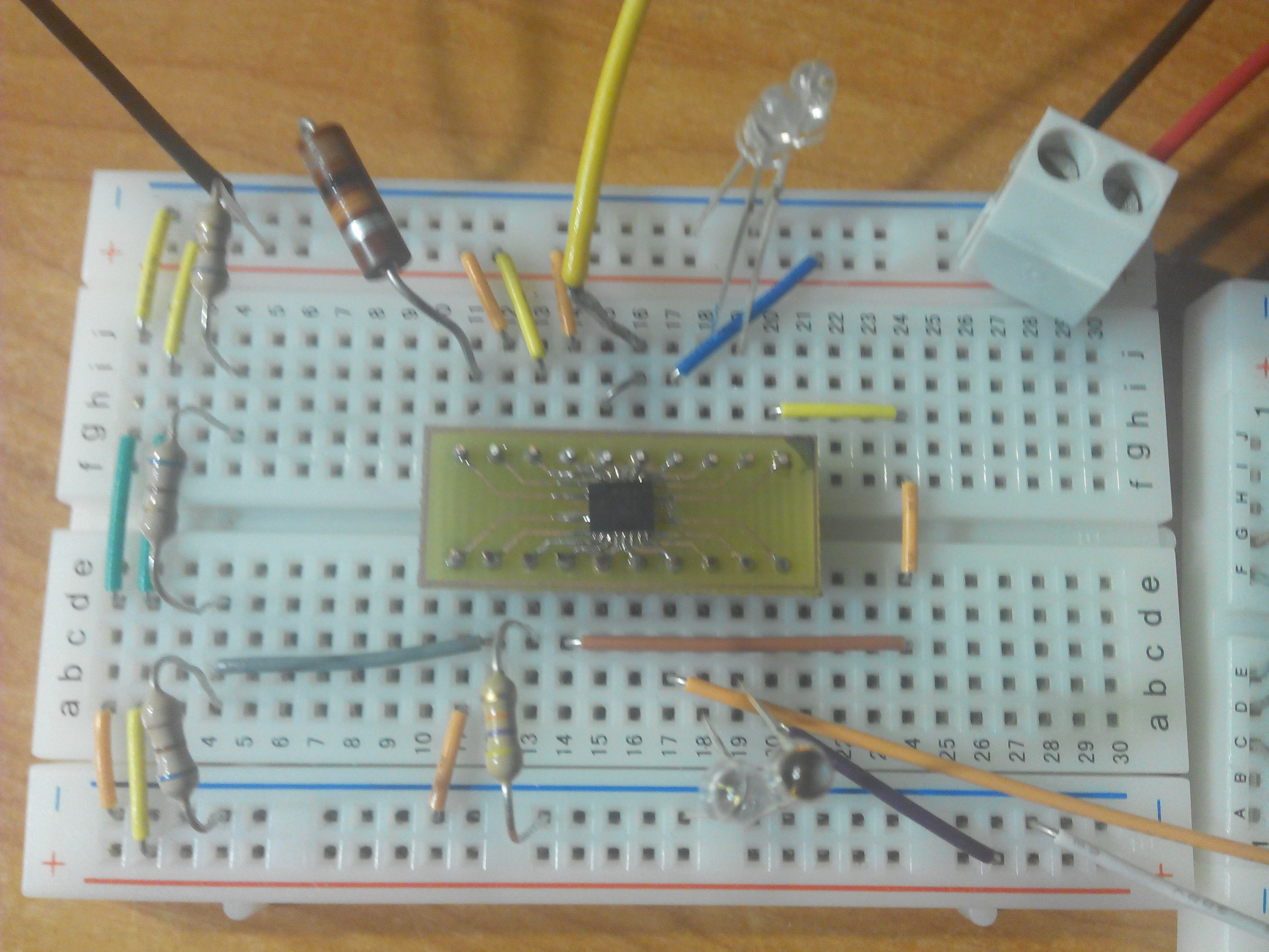
I am trying to develop a prototype on a solderless protoboard so I converted bq24030 to PDIP package by designing a custom PCB to place it. 

The only thing that works is that the bq swaps between my 2 power sources (USB and battery), but no charge of the battery occurs, no status LED is turned ON at any time so I am desperate because I have to develop a protoype and I have no idea about what is going on...

My config is: 

- Rdppm: 50 Kohm (5 volts output, I know USB is outputted directly when PSEL is LOW).

- Rset: 10 Kohm (110mA is supposed to occur as battery charging current).

- Both BAT pins, connected together to positive terminal of the battery (negative to ground).

- ISET2,CE : linked to Vdd.

- TMR pin, linked to LDO pin (to disable the charge timer).

- TS pin linked to the third pin of my battery (the one that is not possitive neither negative)

- OUT pins, linked together to the entrance of my system (microcontroller with LEDs).

- USB pin, connected to 5 Volt source (PC power source).

I'm trying to charge a smartphone battery, 3,7 volts - 850 mA.

I

So, bq24030 does nothing as expected, I have read the datasheet carefully for at least, 50 times but I cant find where is the mistake I am doing...

Any idea???

Thanks in advance...

  • Hello Carlos,

    Do you have the spec sheet for the battery? There is a chance that the third pin you are connecting to is not a thermistor. The best way to test if this is creating your problem would be to artificially bias the TS pin of the BQ24030 so you know that it is in a charging temperature range. You can also simply take a multimeter and probe the TS pin to see what the voltage present there is and if it falls within the the proper range


    Another question I would have is if you you are able to draw current from the OUT pin.

  • Hello Ryan,

    I am read a few minutes ago, the datasheet of the battery. You were right, the third pin I was connecting TS pin to, is a battery size pin, and its voltage measured from the common ground of the circuit, is always 0 Volts...

    Can I use this battery somehow? Can I trick the bq to disable temperature checking?

    In response to you second question, yes, when I power the system from both the battery or the USB, I draw current to my system and it works perfectly.

    Thanks in advance!

  • Hello Carlos,

    If you want to bypass the temperature sensing features of the this device you simply need to bias the TS pin to a voltage between the low and high temperature triggering thresholds shown on Pg. 6 of the datasheet.

  • Hi Ryan,

    I have already tried this by making a voltage divisor between USB and GND, making voltage in TS pin equal to 1,5 Volts but even so, the chargement of the battery does not start. The effect that is triggered when I switch on the USB power is that the consumption of current from the battery drops to 0 but this current doesnt change its polarity, indicating the battery chargement has not begun...

    One question, what is the purpose of having 2 BAT pins? I say so, because when I plung my Bat possitive terminal to the BAT 2 (pin 6), it supplys power to the system, but should I plung it into BAT 1 (pin 5), it does not, so... Is this normal running or my circuit is broken?

    Thanks in advance.

  • Hello Carlos,

    Could you upload a copy of your schematic? That would help me understand you system better.

    What do you mean by Vdd? Since there is no Vdd pin and there are three potential power rails between the two inputs and the OUT pin.

    The reason for having two BAT pins is to distribute the output current across two pins on the output to create a lower impedance connection. They are not connected differently internal so if you are having issues when you selectively connect either of these pins it is probable that there is a short or an undesirable connection to another part of the circuit in your prototyping setup.


    Have you tried running your system with an EVM?

  • Hello Ryan,

    I am using a custom PCB with bq24030 soldered on it, because I ordered directly the ICs rather than ordering an evaluation module first... So I think I did not fix the IC properly and that could be the reason i have falling into problems... I have also tried to solder very thin wires to each one of the IC pins, I know this is quite dfficult but I have a lot of practice with this micro-operations.

    Anyway, tomorrow I am going to go to the lab so as to built other chips on custom PCBs and, if none runs properly, I am going to order an EVM. 

    I was looking for bq24030 EVM and I realizes it is a great deal expensive, otherwise, bq24031 EVM is much less expensive... (from 149 USD (bq24030EVM) to 49 USD (bq24031EVM)), do you know what is the difference between the 2 evaluation modules apart from the IC obviously ?

    Thanks in advance.

    Here, my circuit:

  • Hello Carlos,

    The EVM for the BQ24030 and BQ24031 are the same board so if you ordered the BQ24031EVM you could remove the BQ24031 and place the BQ24030 in its place. I am note sure what is causing the substantial pricing difference so I would recommend simply obtaining the less expensive EVM and placing that chip that you want on it.

    It is possible that you might have shorted some of the pins during you soldering or that you might have damaged the IC through heating it too much when you were placing all of the break out wires.

    How has the testing today been going?