This thread has been locked.

If you have a related question, please click the "Ask a related question" button in the top right corner. The newly created question will be automatically linked to this question.

Bad capacity prediction and rough temperature/current correction with bq34z100

Other Parts Discussed in Thread: BQ34Z100, BQ27510, BQ27350

Hello.

I trying use bq34z100 with 4-parallel NCR18650 Panasonic (2900ma) battery set, but after testing got very bad results. Please check my records, maybe you can give me recommendation for improving working with this ICs.

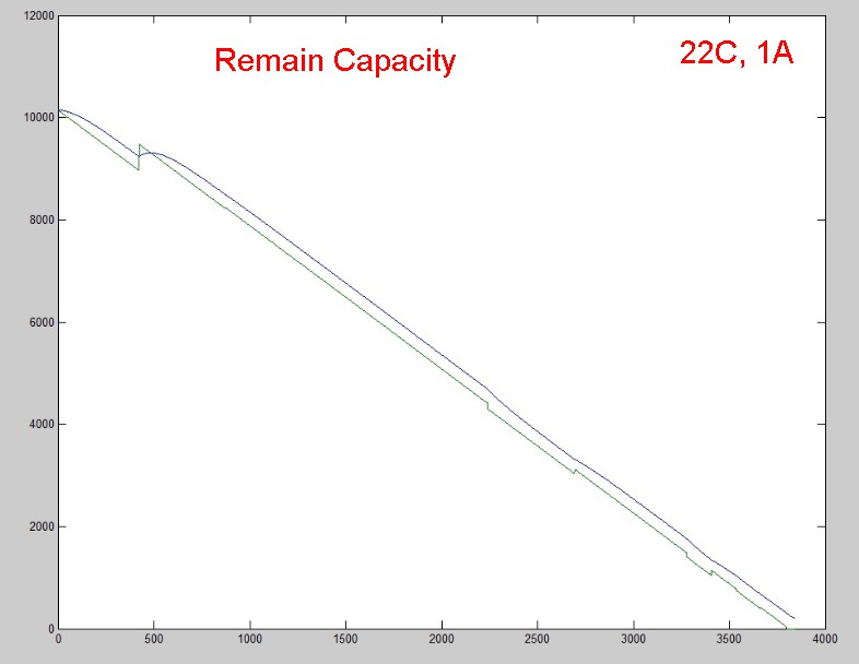
At first I set config for my battery specification and received golden image (file "config.gg"). Here three graphs of Remaining Capacity prediction in calibration progress when discharging (graph1).

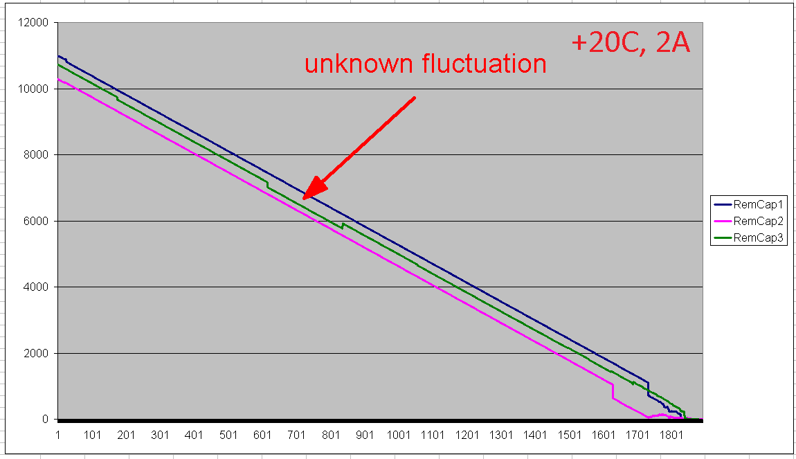
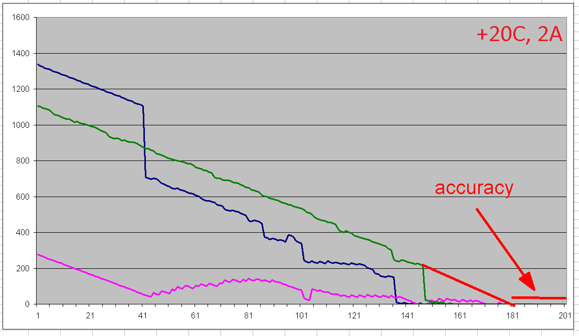
As you can see, the last (3) curve has a very good precision, if draw a line for the end (graph2 is zooming) we get about 1.1% accuracy in overall. But shape of the graph is not very good for real use, because it have unknown step-fluctuation (with sharp jumping of % capacity about 2%, see graph1). Besides, prediction capacity is over before voltage reached minimal value. Please see graph3 with end of third calibration curve with imposed voltage curve. As I understand, prediction capacity must be related with current voltage according chemical table (for my type of battery NCR18650, wich be uploaded before calibration), but correction too juddering, even it is.

Here measurements on a less current ~1.3A, results not bad (see graph4), exept step-down at the end.

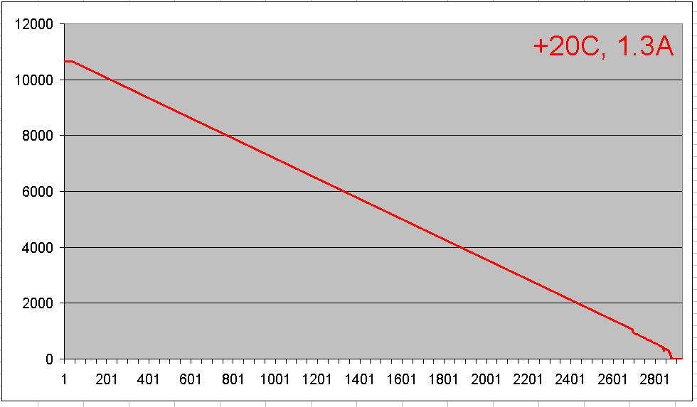
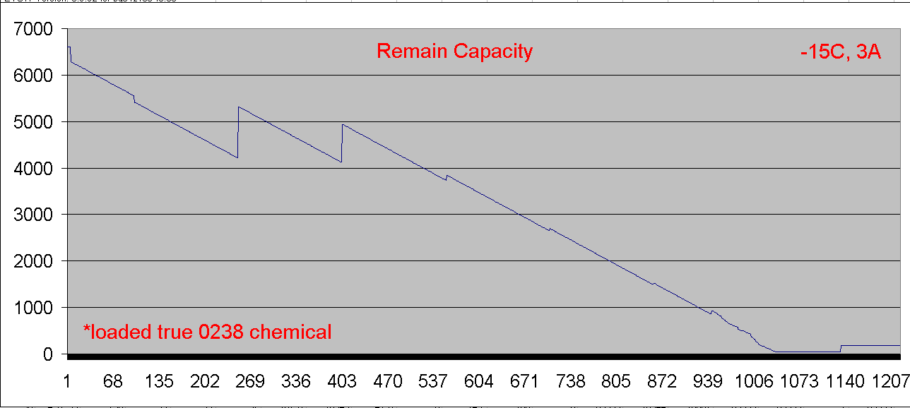
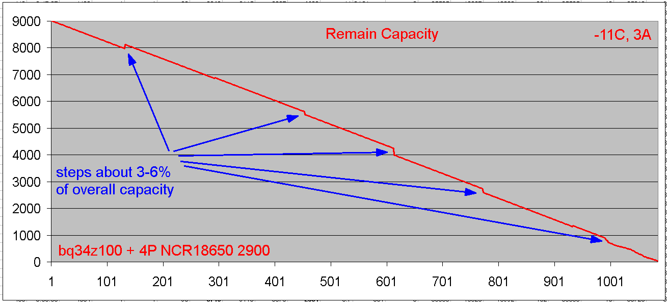
Here measurements on a larger current ~4A (see graph5), and results not very good - curve of remaining capacity prediction fall down on about 9% earlier of real capacity. And again we see a several big step-fluctuation (as I understand this is may be a fault of comparing with chemical table).

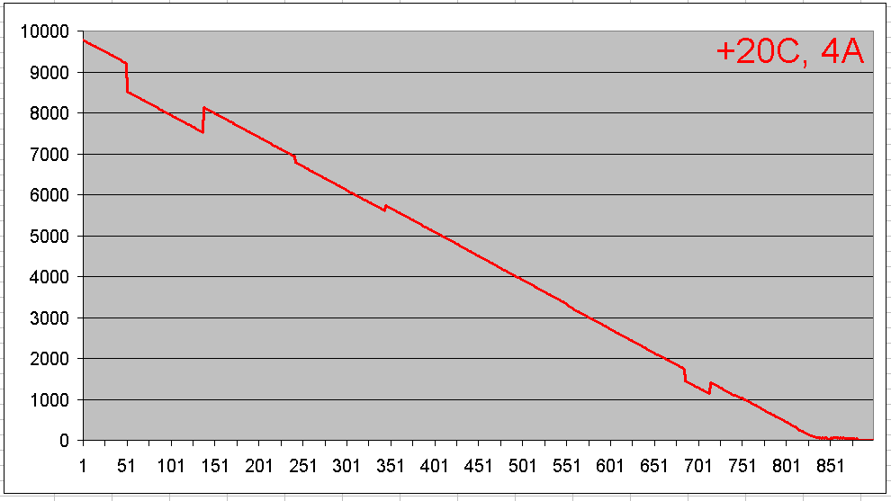
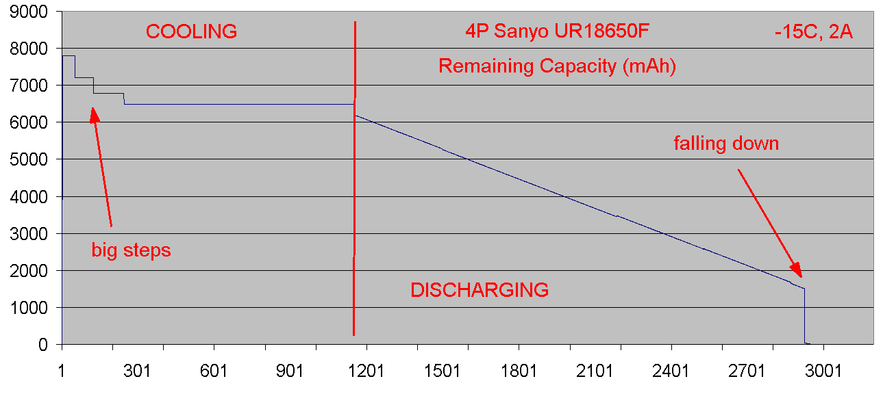
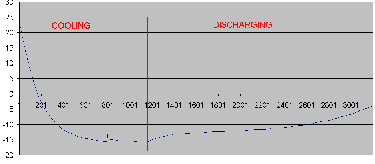
And next battery prediction testing at different from calibrated temperature on about -16C. Results very poor. (see graph 6) Curve has giant steps without any correlation with real capacity.

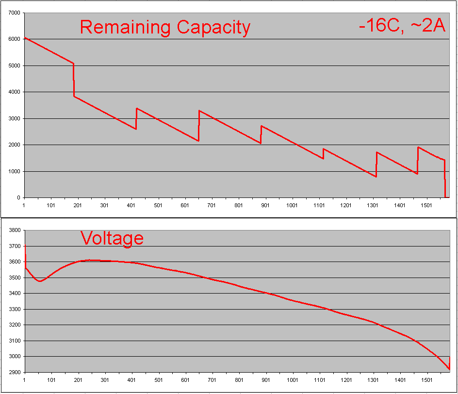
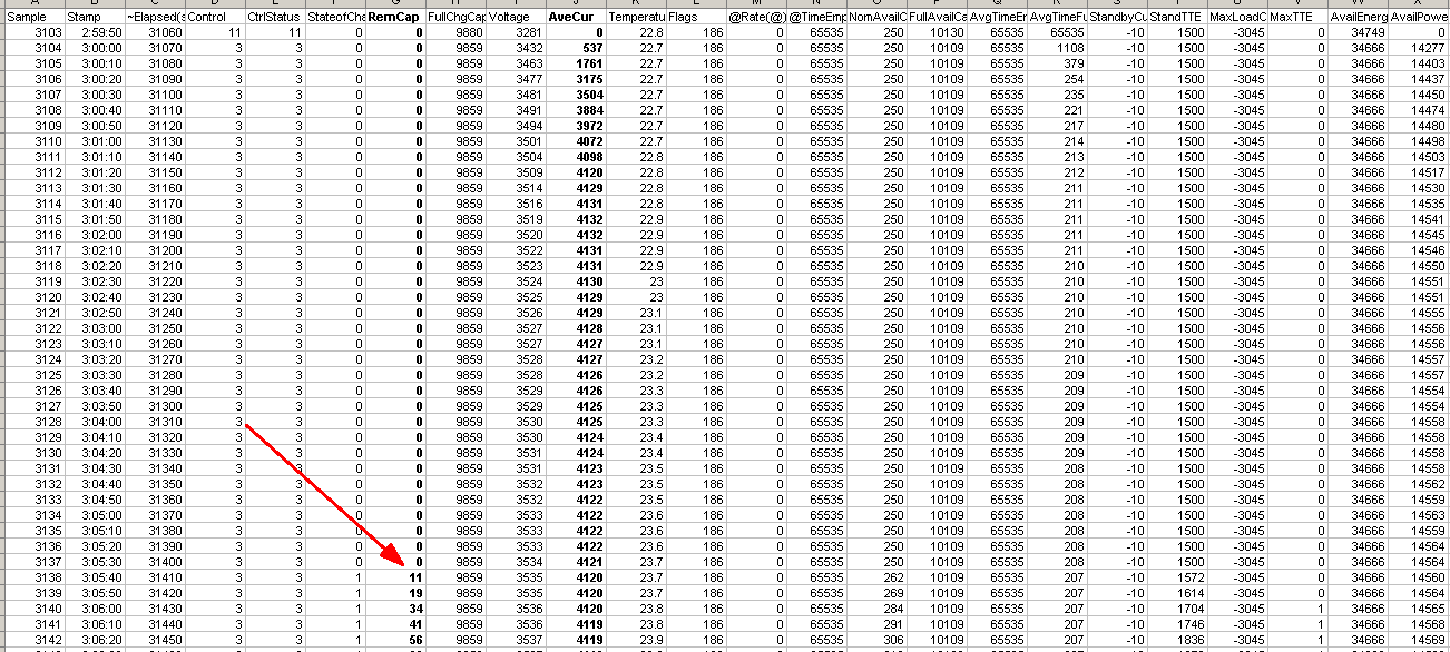
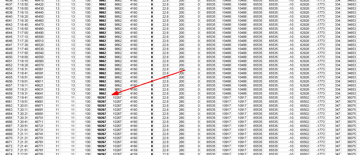
However, once I noticed, that counting on charging is not work correctly at the end of charge. Capacity counting just stops on certain value and not count some % of energy. Its happend while charging battery after it was fully discharged at -16C temperature, then heated by the room temperature with restoring remaining capacity to about 2000ma. See graph7.


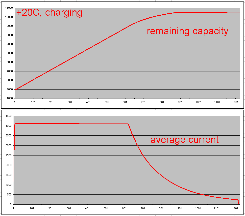
So, as I see capacity prediction is not work correctly, but cant find reason for this.

Q1. Whether it is possible smoothing graph of remaining capacity prediction to eliminate step-correction of prediction?
Q2. Is it possible eliminate graph break at the end and strech it according minimal voltage value?
Q3. How to reach good working bq34z100 with my battery on terms different from first calibration (20C, 2A)?
Q4. Why there was a failure of capacity counting on charging?

PS: Im sure that chemical of my battery is the same as I choose in chemical selection list (NCR18650 2900ma code 0238), temperature probe has good thermal contact with battery, was placed between nearby elements and is correctly type (103AT 3435K), all elements brand-new and fresh. I attach photo of my testing setup and full log in four files of all my tests.

I will be grateful for any advice.

With best regards, Viktor.

0028.01__discharge1.log

1070.01__discharge2.log

3312.01__discharge3-cool.log

7416.01__discharge4-cool.log

[Header]
bq EVSW Version = 0.9.90	
DeviceName = bq34z100 v0.06
Time = 14.04.2014 16:56:57	


[Safety(Configuration)]
OT Chg = 55.0
OT Chg Time = 2
OT Chg Recovery = 50.0
OT Dsg = 60.0
OT Dsg Time = 2
OT Dsg Recovery = 55.0
[Charge Inhibit Cfg(Configuration)]
Chg Inhibit Temp Low = 0.0
Chg Inhibit Temp High = 45.0
Temp Hys = 5.0
[Charge(Configuration)]
Suspend Low Temp = -5.0
Suspend High Temp = 55.0
[Charge Termination(Configuration)]
Taper Current = 300
Min Taper Capacity = 4
Cell Taper Voltage = 150
Current Taper Window = 40
TCA Set % = 99
TCA Clear % = 95
FC Set % = 100
FC Clear % = 98
DODatEOC Delta T = 10.0
[Data(Configuration)]
Rem Cap Alarm = 100
Initial Standby = -10
Initial MaxLoad = -500
Manuf Date = 01-ѳ�-1980
Ser. Num. = 0001
Cycle Count = 3
CC Threshold = 10440
Design Capacity = 11600
Design Energy = 32000
SOH Load I = -4000
TDD SOH Percent = 90
Cell Charge Voltage T1-T2 = 4200
Cell Charge Voltage T2-T3 = 4200
Cell Charge Voltage T3-T4 = 4100
Charge Current T1-T2 = 10
Charge Current T2-T3 = 50
Charge Current T3-T4 = 30
JEITA T1 = 0
JEITA T2 = 10
JEITA T3 = 45
JEITA T4 = 55
ISD Current = 10
ISD I Filter = 127
Min ISD Time = 7
Design Energy Scale = 1
Device Name = nk2bat
Manufacturer Name = vrp-lights
Device Chemistry = LION
[Discharge(Configuration)]
SOC1 Set Threshold = 660
SOC1 Clear Threshold = 800
SOCF Set Threshold = 330
SOCF Clear Threshold = 450
Cell BL Set Volt Threshold = 3100
Cell BL Set Volt Time = 2
Cell BL Clear Volt Threshold = 3200
Cell BH Set Volt Threshold = 4300
Cell BH Volt Time = 2
Cell BH Clear Volt Threshold = 4200
[Manufacturer Data(Configuration)]
Pack Lot Code = 0000
PCB Lot Code = 0000
Firmware Version = 0000
Hardware Revision = 0000
Cell Revision = 0000
DF Config Version = 0000
[Integrity Data(Configuration)]
Static Chem DF Checksum = 0000
[Lifetime Data(Configuration)]
Lifetime Max Temp = 30.0
Lifetime Min Temp = 15.2
Lifetime Max Chg Current = 4156
Lifetime Max Dsg Current = -2061
Lifetime Max Pack Voltage = 4198
Lifetime Min Pack Voltage = 2855
[Lifetime Temp Samples(Configuration)]
LT Flash Cnt = 39
[Registers(Configuration)]
Pack Configuration = 0161
Pack Configuration B = FF
Pack Configuration C = 30
LED_Comm Configuration = 00
Alert Configuration = 0000
Number of series cell = 1
[Lifetime Resolution(Configuration)]
LT Temp Res = 1.0
LT Cur Res = 100
LT V Res = 25
LT Update Time = 60
[LED Display(Configuration)]
LED Hold Time = 4
[Power(Configuration)]
Flash Update OK Cell Volt = 2800
Sleep Current = 10
FS Wait = 0

[Manufacturer Info(System Data)]
Block A 0 = 00
Block A 1 = 00
Block A 2 = 00
Block A 3 = 00
Block A 4 = 00
Block A 5 = 00
Block A 6 = 00
Block A 7 = 00
Block A 8 = 00
Block A 9 = 00
Block A 10 = 00
Block A 11 = 00
Block A 12 = 00
Block A 13 = 00
Block A 14 = 00
Block A 15 = 00
Block A 16 = 00
Block A 17 = 00
Block A 18 = 00
Block A 19 = 00
Block A 20 = 00
Block A 21 = 00
Block A 22 = 00
Block A 23 = 00
Block A 24 = 00
Block A 25 = 00
Block A 26 = 00
Block A 27 = 00
Block A 28 = 00
Block A 29 = 00
Block A 30 = 00
Block A 31 = 00

[IT Cfg(Gas Gauging)]
Load Select = 1
Load Mode = 0
Max Res Factor = 15
Min Res Factor = 3
Ra Filter = 500
Fast Qmax Start DOD % = 92
Fast Qmax End DOD % = 96
Fast Qmax Start Volt Delta = 200
Cell Terminate Voltage = 2950
Cell Term V Delta = 50
ResRelax Time = 200
User Rate-mA = 0
User Rate-Pwr = 0
Reserve Cap-mAh = 0
Reserve Energy = 0
Max Scale Back Grid = 4
Cell Max DeltaV = 200
Cell Min DeltaV = 0
Max Sim Rate = 2
Min Sim Rate = 20
Ra Max Delta = 44
Qmax Max Delta % = 5
Cell DeltaV Max Delta = 10
Fast Scale Start SOC = 10
Charge Hys V Shift = 40
[Current Thresholds(Gas Gauging)]
Dsg Current Threshold = 50
Chg Current Threshold = 75
Quit Current = 30
Dsg Relax Time = 60
Chg Relax Time = 60
Quit Relax Time = 1
Cell Max IR Correct = 400
[State(Gas Gauging)]
Qmax Cell 0 = 11274
Cycle Count = 3
Update Status = 06
Cell V at Chg Term = 4195
Avg I Last Run = -2040
Avg P Last Run = -7366
Cell Delta Voltage = 1
T Rise = 20
T Time Constant = 1000

[OCVa Table(OCV Table)]
Chem ID = 0107

[R_a0(Ra Table)]
Cell0 R_a flag = 0000
Cell0 R_a 0 = 22
Cell0 R_a 1 = 21
Cell0 R_a 2 = 41
Cell0 R_a 3 = 54
Cell0 R_a 4 = 64
Cell0 R_a 5 = 91
Cell0 R_a 6 = 113
Cell0 R_a 7 = 129
Cell0 R_a 8 = 134
Cell0 R_a 9 = 140
Cell0 R_a 10 = 153
Cell0 R_a 11 = 180
Cell0 R_a 12 = 186
Cell0 R_a 13 = 173
Cell0 R_a 14 = 401
[R_a0x(Ra Table)]
xCell0 R_a flag = 0055
xCell0 R_a 0 = 34
xCell0 R_a 1 = 32
xCell0 R_a 2 = 62
xCell0 R_a 3 = 82
xCell0 R_a 4 = 98
xCell0 R_a 5 = 139
xCell0 R_a 6 = 172
xCell0 R_a 7 = 197
xCell0 R_a 8 = 204
xCell0 R_a 9 = 213
xCell0 R_a 10 = 233
xCell0 R_a 11 = 274
xCell0 R_a 12 = 283
xCell0 R_a 13 = 264
xCell0 R_a 14 = 611

[Data(Calibration)]
CC Gain = 10.107
CC Delta = 10.088
CC Offset = -0.69
Board Offset = 0
Int Temp Offset = 0.0
Ext Temp Offset = 0.0
Voltage Divider = 4992
[Current(Calibration)]
Deadband = 5

[Codes(Security)]
Sealed to Unsealed = 36720414
Unsealed to Full = FFFFFFFF
Authen Key3 = 01234567
Authen Key2 = 89ABCDEF
Authen Key1 = FEDCBA98
Authen Key0 = 76543210

  • Viktor, 

    I have been out of the office on vacation, so I am sorry about the delay. I have not had a chance to review all og the log files yet, but I reviewed the gg file. It shows that ChemID 107 is loaded. Are you sure that you loaded ChemID 0238 when you ran the tests. 

    Regards
    Tom

  • Hello Tom

    Thanks for your answer. You right, this testing has been not correct, because of wrong chemical selection. But its not my first testing and at previous I received bad results too. This is my 4P x Sanyo UR18650FJ setup results (which chemical selection mistakenly still in new design). At first on slowly cooling battery in thermostat Remain Capacity prediction has very innacurate change. At second - unexpected falling down at the end. But I use not fresh battery cells for this test, maybe it is reason of this...

    Now I'm trying recheck my 4x2900 Panasonic setup, which must be in final design. I tried keep calibration and just reload correct 0238 chemical, but got bad results again, maybe because of wrong previous calibration.


    So I send command reset (0x0041) and begin new calibration with correct chemical id. At near time I will write new results of my testing.
    However, I notice some strange in current log file during recalibration - Remain Capacity is not calculated on start charging (about first 6 minutes) and stop change values when FC bit set... but after 35 minutes its changed to real value. I attach a piece of log with one charging cycle with this strangeness and new config file.

    [Header]
    bq EVSW Version = 0.9.90	
    DeviceName = bq34z100 v0.06
    Time = 13.05.2014 11:32:15	
    
    
    [Safety(Configuration)]
    OT Chg = 55.0
    OT Chg Time = 2
    OT Chg Recovery = 50.0
    OT Dsg = 60.0
    OT Dsg Time = 2
    OT Dsg Recovery = 55.0
    [Charge Inhibit Cfg(Configuration)]
    Chg Inhibit Temp Low = 0.0
    Chg Inhibit Temp High = 45.0
    Temp Hys = 5.0
    [Charge(Configuration)]
    Suspend Low Temp = -5.0
    Suspend High Temp = 55.0
    [Charge Termination(Configuration)]
    Taper Current = 300
    Min Taper Capacity = 4
    Cell Taper Voltage = 150
    Current Taper Window = 40
    TCA Set % = 99
    TCA Clear % = 95
    FC Set % = -1
    FC Clear % = 98
    DODatEOC Delta T = 10.0
    [Data(Configuration)]
    Rem Cap Alarm = 100
    Initial Standby = -10
    Initial MaxLoad = -500
    Manuf Date = 01-ѳ�-1980
    Ser. Num. = 0001
    Cycle Count = 0
    CC Threshold = 10440
    Design Capacity = 11600
    Design Energy = 32000
    SOH Load I = -4000
    TDD SOH Percent = 80
    Cell Charge Voltage T1-T2 = 4200
    Cell Charge Voltage T2-T3 = 4200
    Cell Charge Voltage T3-T4 = 4100
    Charge Current T1-T2 = 10
    Charge Current T2-T3 = 50
    Charge Current T3-T4 = 30
    JEITA T1 = 0
    JEITA T2 = 10
    JEITA T3 = 45
    JEITA T4 = 55
    ISD Current = 10
    ISD I Filter = 127
    Min ISD Time = 7
    Design Energy Scale = 1
    Device Name = nk2bat
    Manufacturer Name = vrp-lights
    Device Chemistry = LION
    [Discharge(Configuration)]
    SOC1 Set Threshold = 660
    SOC1 Clear Threshold = 800
    SOCF Set Threshold = 330
    SOCF Clear Threshold = 450
    Cell BL Set Volt Threshold = 3100
    Cell BL Set Volt Time = 2
    Cell BL Clear Volt Threshold = 3200
    Cell BH Set Volt Threshold = 4300
    Cell BH Volt Time = 2
    Cell BH Clear Volt Threshold = 4200
    [Manufacturer Data(Configuration)]
    Pack Lot Code = 0000
    PCB Lot Code = 0000
    Firmware Version = 0000
    Hardware Revision = 0000
    Cell Revision = 0000
    DF Config Version = 0000
    [Integrity Data(Configuration)]
    Static Chem DF Checksum = 5A60
    [Lifetime Data(Configuration)]
    Lifetime Max Temp = 30.0
    Lifetime Min Temp = -18.1
    Lifetime Max Chg Current = 4156
    Lifetime Max Dsg Current = -4161
    Lifetime Max Pack Voltage = 4198
    Lifetime Min Pack Voltage = 2839
    [Lifetime Temp Samples(Configuration)]
    LT Flash Cnt = 62
    [Registers(Configuration)]
    Pack Configuration = 0161
    Pack Configuration B = FF
    Pack Configuration C = 30
    LED_Comm Configuration = 00
    Alert Configuration = 0000
    Number of series cell = 1
    [Lifetime Resolution(Configuration)]
    LT Temp Res = 1.0
    LT Cur Res = 100
    LT V Res = 25
    LT Update Time = 60
    [LED Display(Configuration)]
    LED Hold Time = 4
    [Power(Configuration)]
    Flash Update OK Cell Volt = 2800
    Sleep Current = 10
    FS Wait = 0
    
    [Manufacturer Info(System Data)]
    Block A 0 = 00
    Block A 1 = 00
    Block A 2 = 00
    Block A 3 = 00
    Block A 4 = 00
    Block A 5 = 00
    Block A 6 = 00
    Block A 7 = 00
    Block A 8 = 00
    Block A 9 = 00
    Block A 10 = 00
    Block A 11 = 00
    Block A 12 = 00
    Block A 13 = 00
    Block A 14 = 00
    Block A 15 = 00
    Block A 16 = 00
    Block A 17 = 00
    Block A 18 = 00
    Block A 19 = 00
    Block A 20 = 00
    Block A 21 = 00
    Block A 22 = 00
    Block A 23 = 00
    Block A 24 = 00
    Block A 25 = 00
    Block A 26 = 00
    Block A 27 = 00
    Block A 28 = 00
    Block A 29 = 00
    Block A 30 = 00
    Block A 31 = 00
    
    [IT Cfg(Gas Gauging)]
    Load Select = 1
    Load Mode = 0
    Max Res Factor = 15
    Min Res Factor = 3
    Ra Filter = 500
    Fast Qmax Start DOD % = 92
    Fast Qmax End DOD % = 96
    Fast Qmax Start Volt Delta = 200
    Cell Terminate Voltage = 2950
    Cell Term V Delta = 50
    ResRelax Time = 200
    User Rate-mA = 0
    User Rate-Pwr = 0
    Reserve Cap-mAh = 0
    Reserve Energy = 0
    Max Scale Back Grid = 4
    Cell Max DeltaV = 200
    Cell Min DeltaV = 0
    Max Sim Rate = 2
    Min Sim Rate = 20
    Ra Max Delta = 44
    Qmax Max Delta % = 5
    Cell DeltaV Max Delta = 10
    Fast Scale Start SOC = 10
    Charge Hys V Shift = 40
    [Current Thresholds(Gas Gauging)]
    Dsg Current Threshold = 50
    Chg Current Threshold = 75
    Quit Current = 30
    Dsg Relax Time = 60
    Chg Relax Time = 60
    Quit Relax Time = 1
    Cell Max IR Correct = 400
    [State(Gas Gauging)]
    Qmax Cell 0 = 11000
    Cycle Count = 0
    Update Status = 00
    Cell V at Chg Term = 4195
    Avg I Last Run = -2891
    Avg P Last Run = -9863
    Cell Delta Voltage = 2
    T Rise = 20
    T Time Constant = 1000
    
    [OCVa Table(OCV Table)]
    Chem ID = 0238
    
    [R_a0(Ra Table)]
    Cell0 R_a flag = 0555
    Cell0 R_a 0 = 117
    Cell0 R_a 1 = 119
    Cell0 R_a 2 = 96
    Cell0 R_a 3 = 85
    Cell0 R_a 4 = 66
    Cell0 R_a 5 = 49
    Cell0 R_a 6 = 51
    Cell0 R_a 7 = 42
    Cell0 R_a 8 = 46
    Cell0 R_a 9 = 55
    Cell0 R_a 10 = 74
    Cell0 R_a 11 = 108
    Cell0 R_a 12 = 205
    Cell0 R_a 13 = 368
    Cell0 R_a 14 = 7439
    [R_a0x(Ra Table)]
    xCell0 R_a flag = FFFF
    xCell0 R_a 0 = 160
    xCell0 R_a 1 = 163
    xCell0 R_a 2 = 192
    xCell0 R_a 3 = 258
    xCell0 R_a 4 = 229
    xCell0 R_a 5 = 191
    xCell0 R_a 6 = 221
    xCell0 R_a 7 = 186
    xCell0 R_a 8 = 201
    xCell0 R_a 9 = 247
    xCell0 R_a 10 = 326
    xCell0 R_a 11 = 480
    xCell0 R_a 12 = 904
    xCell0 R_a 13 = 1622
    xCell0 R_a 14 = 32767
    
    [Data(Calibration)]
    CC Gain = 10.107
    CC Delta = 10.088
    CC Offset = -0.69
    Board Offset = 0
    Int Temp Offset = 0.0
    Ext Temp Offset = 0.0
    Voltage Divider = 4992
    [Current(Calibration)]
    Deadband = 5
    
    [Codes(Security)]
    Sealed to Unsealed = 36720414
    Unsealed to Full = FFFFFFFF
    Authen Key3 = 01234567
    Authen Key2 = 89ABCDEF
    Authen Key1 = FEDCBA98
    Authen Key0 = 76543210
    

    6406.06_first_discharge_post.log

  • I completed calibration and done prediction testing. Results much better that first time I posted, but tendency of step-correction still remain. However, when I used bq27510 I obtained curves, which was not ideal flat, but deviation was very smoothly in time.

    So, can curve of Remain Capacity be smoothed in bq34z100 to obtain prediction without steep drops/rises in time?

  • Viktor,

    The bq34z100 does not have a smoothing filter, so you may see steps in RM and FCC as the device runs simulations during discharge.

    Tom

  • Tom,

    I tried to apply filtering to data I'v got, but results are still unacceptable. If I install this on real device users can be confused by SOC increase when battery is actually discharged.

    So, can bq34z100 give discharge prediction curve that after smoothing be overall continuously decreased on constant current load in various value (about 1/50C to 1/3C) and temperature range (-20...+40C)? Maybe, you can give an advice for filtering algorithm to be used with date returned by my IC?

    If not, please help me to select IC that returns nice, smooth and accurate capacity predictions.

    Viktor

  • Viktor,

    You do not need to use a multi-cell device since you have a 1S4P configuration. Can you use the bq27510 that you found to provide acceptable performance?

    Tom

  • Tom,

    Our assembly house can't handle SON package reliably. So I want to use part with TSSOP or silimar (not too fine pitch) package to get high production yeld.

    Viktor

  • Viktor,

    Unfortunately, our high performance single cell devices a only offered in SON packages. We have some older CEDV type gauging solutions that can support single cell and they are offered in leaded packages. They are the be20xx devices.

    Tom

  • Tom,

    I know about bq20X ICs, but I search only with Impendance Track technology.. as I think its can get much better prediction. How about bq27350, does it provide good prediction, like bq27510? I am a little confused by the revision date by 2009 year.

    Viktor

  • Viktor,

    I do not work with the single cell gauges, so one of the other apps engineers will let you know which will be the best choice.

    Tom

  • Ok, thanks. Hope for soon response...