This thread has been locked.

If you have a related question, please click the "Ask a related question" button in the top right corner. The newly created question will be automatically linked to this question.

iso5500 gate mosfet gate driver

Hi,

I am student in process of designing a inverter. I will be using the ISO5500 for a full bridge converter, however, I will be using an analog PWM instead of micro controller. If I am using the inverting configuration (PWM will be applied to VIN-), can I connect all the four ISO5500 FAULT to each VIN+ as a safety measure (note no microcontroller is used so the FAULTs are going only to the VIN+ and the bypass capacitor). Also can I control the four RESET manually by connecting the four RESETS to a monostable vibrator (such as 74ls123) and inject a pulse by a push button whenever there is an error ?also can you send me the CAD or the foot print for the device I could not find it . thank you

Majdi

  • Hello Majdi,

    I don't think this will work, although it is a very creative idea. I assume the reasoning is that if you tie V+ to the Fault pin, when the Fault pin goes high, the V+ rises high to the same level as V- and shuts off the ISO550 pwm output, or actually drives the output low. The problem is once the ISO5500 shuts off it will not try to start again after the fault is cleared because the error signal is latched into the internal RS flipflop. You would need to drive this pin low to restart the driver after a fault. 

    I would not recommend using a manual push button for stopping errors. Micro-controllers with usec reaction times are not fast enough to stop an IGBT from failing, let alone the incredibly slow reaction time of a human being 2 or 3 second for people under 18.  

    Hope this helps,

    Chuck Sampson

  • Hi Chuck,

    what is your suggestion if I will not be using a microcontroller as the  PWM device? should I just connect the RESET to the PWM Vin+ for a non-inverting input? what about the FAULT for the non-inverting input where should I connect to?

    Thank you

    majdi

  • Majdi,

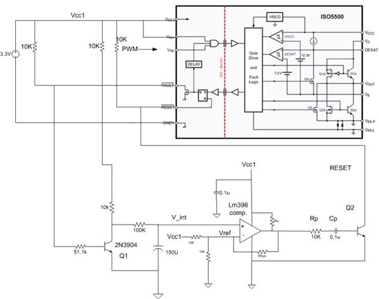
    You can keep the V+ set high for an inverting PWM. You need to emulate the micro-controller with what is known as "glue logic". An example is shown in the suggested schematic below:

    If you examine the timing diagram in Figure 60 of the data sheet you will see that the uC keeps reset pin high via the output port O/P. The circuit I propose keeps Reset pin high with a 10k pull up resistor to Vcc. Q1 is kept on while the Reset pin is high to ensure that the voltage across the integrating capacitor (150u) is close to zero volts,  When the internal Fault signal goes high, the PWM control is blocked. It does not return until Reset is pulled low. So when Fault goes high, notFault signal goes low. Q1 is turned off and effectively connects the integrator circuit consisting of a 100 K resistor and 150 uF capacitor tied to the Q1 collector to Vcc. Once the Vcc voltage is connected to the RC network the 150uF capacitor begins to charge. Then when the capacitor voltage V_int reaches the value of Vref, +/- the hysteresis voltage, the output of the LM396 goes high and pulses Q2 low.The length of the pulse is determined by the RC network connected between the output of the comparator and Q2's base. You will need to adjust these values to get the right pulse width for re-setting the internal flip flop.

    I haven't tested this circuit. I have used circuits like this in the past. The RC integrator has a time constant of 15 seconds, so it should clear the internal flip flop at that rate or higher depending on where you set the reference voltage Vref. If the fault has not cleared, this cycle will repeat every 10 or 15 seconds. This is called a hiccup mode or more formally a "stable limit cycle oscillation".

    I put this circuit together in about 20 min. so you need re-check to see if I missed something. It is meant as suggestion and should be carefully implemented. I would test it in SPICE first before actually building it if you can.

    Chuck