This thread has been locked.

If you have a related question, please click the "Ask a related question" button in the top right corner. The newly created question will be automatically linked to this question.

UCC28950

In the schematic og teh evaluation module, SLUA560B, SLUU421a, there are gate resistors R7,R10,R15,R16 which function I do not  understand. 

If the purpose of these resistors is to have a discharge path to the gate before start up, they seem useless as this is acomplished by the secondary of the gate transformer.

  • Francesc,

    I agree that these resistors serve no purpose. I have designed two fb zvt transformers and did not include these components in my high side gate drives.

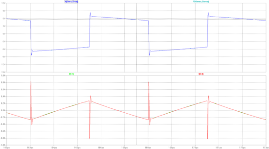
    I implemented  a SPICE model of a high side gate drive using typical values. After running the simulations, I observed the waveforms. As you can see there is no difference between the two circuits.

    I have been in design reviews where the 10k ohm resistors were added to prevent the false turn on of the mosfet during susceptibility testing. The high impedance node of the mosfet is susceptible to high frequency noise, so that could be a possible reason for them. Otherwise I can see no difference. If someone can point out the errors in my analysis, please do. I would like to be enlightened :).