This thread has been locked.

If you have a related question, please click the "Ask a related question" button in the top right corner. The newly created question will be automatically linked to this question.

Question about UCC27210 behavior.

Genius 4220 points
Other Parts Discussed in Thread: UCC27210, LM5102, UCC27712

Hi,

If we keep both input (HI and LI) HIGH state, will both output(HO and LO) become HIGH?

Does UCC27210( or other Gate driver) have some function which prevent the condition that

both output become high simultaneously like LINEAR TECH LT1336?

http://cds.linear.com/docs/en/datasheet/1336fa.pdf

(As for the LT1336, If we keep both input  HIGH state, both output  become LOW state.)

Thanks 

Go

  • Hi Go,

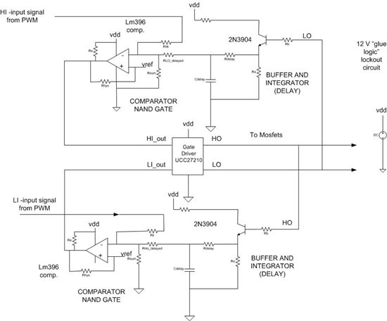
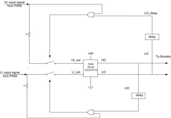
    I am not a TI rep, and I have not used this part before, so I can't say for sure. But judging from the block diagram in the data sheet and looking over the pin functions, I'd say there is no gate lock out feature in the UCC27210. However, you do have to pay for the extra feature: the UCC27210 cost 3.89 ea. and the LT1336 costs 6.00. And the 27210 has some nice features the LT1336 doesn't have, like 120 V boot voltage and high voltage spike immunity at the pin inputs. If want to use the UCC27210 and still have the lockout feature of the 1336 you can add some "glue logic". I have worked out a design idea you may use. (See picture below.) I didn't calculate any of the component values or test the circuit -I am just presenting it as a suggestion. I have used similar circuits before. I have to use comparators because the logic gates work on 5 volt logic. The high logic threshold for the UCC27210 is 5.8V maximum. These extra parts do take up some board space, but they cost less than a 1.00, so your are still less expensive than the LT1336 and you have the high voltage features of the UCC27210.

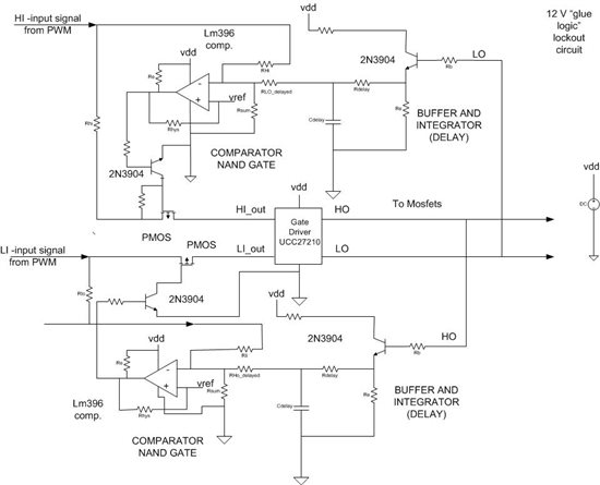
    The circuit is very simple. The HO signal is buffered and delayed to prevent glitches and race conditions. then it is summed with the LI signal. If they are both "high", their sum will be more than Vref and the input to the UCC27210 goes low. Same for the high side.

    Hope this helps,

    Chuck Sampson

  • Chuck,

    You are right that UCC27210 does not have the gate lock out feature.

    Thank you very much for your answer and suggestion!

    Regards

    Kening

  • Hello Kening,

    My circuit suggestion is incomplete. I have added a more detailed one. I will test this circuit sometime this week and get back with the results.

  • Hi

    I consider this to be a good feature. In my application, I want to turn on the low side a few nanoseconds before the high side turns off. If I didn't want to do that, my logic, completely controlled very deterministically from one of the microprocessors, can implement the necessary logic with no external glue logic required.
  • Hello Go,
    I am an applications engineer at TI and will look to answer your questions. As was mentioned with previous responses, the UCC27210 does not have the feature we call input interlock which prevents both outputs from being high.
    TI does have driver solutions with this feature however.
    I noticed the LT1336 is a different class of propagation delay 200-300ns Vs <20ns for UCC27210, and driver current, 1.5A Vs 4A for UCC27210. Also the voltage rating is different. 60V Vs 100V for the UCC27210.
    Can you give some details about your application?
    Is a single input, complimentary output driver suitable in your design?
    What is the voltage rating, driver delay, and driver current that you need for your design?
    A couple of ideas to review, the LM5102 is a two input driver where you can independently control the delays to each output. It is not the same as the interlock however.
    TI has the UCC27712 which does have the interlock feature and driver currents beyond the LT part, and propagation delays lower than the LT part. The voltage rating is considerably higher than the LT device or the UCC27210.

    Regards,
    Richard Herring