


I wonder if it is possible to avoid the use of the shim inductor using the synchronous rectifier drive system shown in the application note SLUA287, where the synchronous rectifier gate signals are taken directly from A and B signals.
The main idea is to use the outputs inductors in the secondary side instead of the shim inductor in the primary side for ZVS.
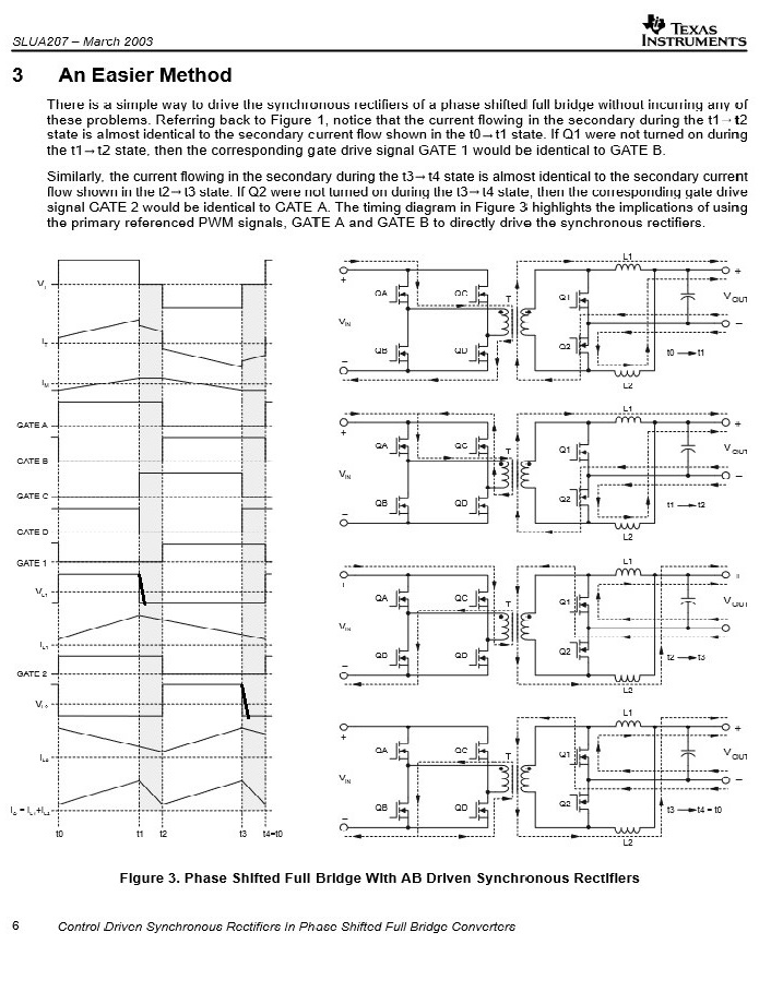
The enclosed drawing is taken from the application note. Q1 gate signal is the same as QB gate signal and Q2 gate signal the same as QA. Following the drawing steps:
1. QA and Q2 are on. Current increases in L1.
2. QD turns off, Q1 remains off. L1 current has to flow through the transformer secondary. At start the voltage is high, about 2xVout so Q1 body diode does not conduct.
Even if magnetizing current is very low, the primary current has to follow the secondary one, so Ip = Iout/2/N: this is a reasonable current to charge fast enough the output capacitances of the MOSFETS at a rate dV/dt = 2 x Co x Iout /(2 N).
QC turns on. Voltage in the transformer is 0.
3. QA and Q2 turn off. L1 current makes QB drain voltage to drop to 0V. During this transition time the current flows through the body diode of Q2. However the average power is very small as this time is very small compared with the period as seen in the example below.
QB and Q1 turn on and current builds up in L2.
4. QC turns off, L2 current, reflected to primary, decreases QD voltage to 0. QD turns on and the cycle restarts.
If all this is true, a nice result would be that the ZVS would occur in all the load range. Just during light loads the transition would be slower, as dV/dt is proportional to current. But this is not a problem as then duty cycle is small and there is plenty of time: just the turn on of QC has to be delayed as necessary.
As an example, the design at which I am working now. Magnetizing current is small and neglected:
Iout = 62A, N = 4, Vout = 28V, Vin (typ) = 300 V. Co(eff) = 360 pF. Cp = 20 pF. fs = 106 kHz.
Primary rise time at full load: (360pF x 2 + 20 pF) x300V /(4 x 31A) = 29 ns
Primary rise time at 1/10 load: tr = 290 ns
Power loss in Q2 owing to body diode conduction, at full load: 31A x 1.2V x 29ns/9.4us = 0.11 W
It seems too good to be true, and I doubt if I have made a mistake somewhere, so I would much appreciate if someone can find a flaw in my arguments ... or confirm them.
