This thread has been locked.

If you have a related question, please click the "Ask a related question" button in the top right corner. The newly created question will be automatically linked to this question.

Dimming Power LED 40W with LM3406HV

Other Parts Discussed in Thread: LM3406HV, LM3406

Hello,

I have a lot of questions about the LM3406HV. I want to drive a power LED (40W) and I have following requirements:

Uin = 42..48V
Uout = 36V ; 1A

1:
I want to dim the Power LED with the normal DIM Input, but I'm not sure, if it is possible with this conditions.
I cant estimate, if I get a wide area of values of duty cycles.
 
I have found in the user guide http://www.ti.com/lit/ug/snva407b/snva407b.pdf on page 3 ,
that the duty cycle dependent on the switching times. The problem is the minimal duty cycle:
D_min = (t_D + t_on_min ) / T

My frequency f is between 340kHz and 390kHz.
And I know  t_on_min = 230ns.

Do I have any chance to estimate t_D ?
My LC filter is L=22uH, C=1uF.

2:
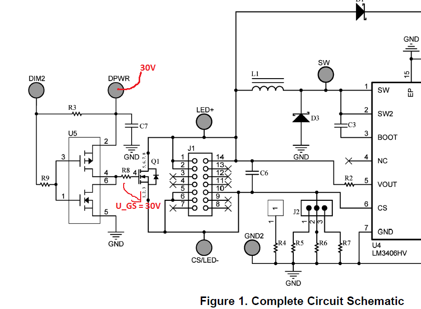
In the user guide  AN-1993 LM3406HV Evaluation Board with 2 Wire
Dimming on page 4 http://www.ti.com/lit/ug/snva407b/snva407b.pdf stands:

"A voltage of up to 30V must be applied to the DPWR pin to operate U5"

But, is 30V not  to high for the mosfet Si4464DY (http://www.vishay.com/docs/72051/72051.pdf) ?
This have a U_GS from +-20V ?

Could you explain it, please?

3:

The n and p-mosfets in U5 http://www.fairchildsemi.com/ds/FD/FDC6333C.pdf get the switching signal in the same time. Is there any problem in the junction?
I mean if one mosfet is still on and the other is already on.

4:
If U_IN swings, for example 42V to 48V. The LM3406HV change the frequency and the duty cycle. What is the advantage of changing both, and not only the duty cycle?

5:
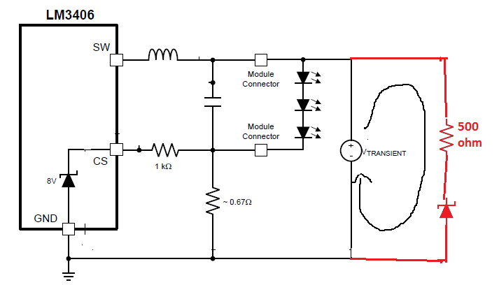
In the datasheet http://www.ti.com/lit/ds/symlink/lm3406.pdf on page 19, the z-diode is between the anode of LEDs and the resistances, to protect the cs input.
Why can't I connect the anode of z-diode with ground?
 
Thank you in advance for reading and answering my questions.

  • Hello,

     Thank you for your interest in LM3406. Please see my comments below:-

    1. T_D is a fixed value and you can estimate it from the left bottom figure on pg.7 of the user guide. It is about 5us.

    2. In your case, the Vds will be 36V. I think 30V for Vgs is high enough for the MOSFET to be in saturation region.

    3. Normally, U5 works as an inverter and the two MOSFET should not be on at the same time. Only if the switching signal's slew rate is low, there might be a chance that both MOSFET are on.

    4. Since the on-time is fixed(set by Ron), if your duty cycle changes, the switching frequency will change automatically. I can’t say if there is advantage, but that’s just how LM3406 works.

    5.The reason why a 500Ohm resistor is in series of the z-diode is to limit the current through the diode when OVP happens. So it is not suggested to connect the anode of z-diode to ground directly.


    Best regards,

    Victor

  • Hi Victor

    thank you for the reply.

    2:
    I think, we have misunderstood us (Sorry, my englisch is not very well).
    Ok, I understand in my case U_DS=36V.

    In the user guide http://www.ti.com/lit/ug/snva407b/snva407b.pdf on page 4, the third sentence:
    "A voltage of up to 30V must be applied to the DPWR pin to operate U5."
    I think, if DPWR=30V, then is at the mosfet Q1 U_GS=30V. In the datasheet, of the mosfet Q1 SI4464DY-E3 is the maximal U_GS=+-20V.
    Q1 becomes damaged?

    Where is my mistake?

    I sketched the voltage in the schematic.


    5:
    Ok, I understand,that I must protect the zdiode.
    Can I connect the zdiode like in the schematic, too ?


    Best regards,

    Dirk

  • Hi Dirk,

    2. You are correct. If you use SI4464DY-E3 as the reference design did, then the maximum voltage of DPWR will be 20V.

    5. Yes, I think you can do OVP that way. Please be aware that since your LED voltage is 36V, you may need to change the 1kOhm resistor value.

    Best regards,

    Victor

  • Hi Victor,


    thank you for your help.

    And thank you for your suggestion to change the 1kohm resistance. The consideration was for 33V in the datasheet.

    Best regards

    Dirk