This thread has been locked.

If you have a related question, please click the "Ask a related question" button in the top right corner. The newly created question will be automatically linked to this question.

TPS62240 shutdown current

Other Parts Discussed in Thread: TPS62240, TPS62740, TPS62240EVM-229

Hello, all

Now we have one inquiry regarding shutdown current on TPS62240 from our customer.

Please refer to the item below, and feedback us with your comment.

When referring page3 of datasheet, this shutdown current (ISD) is defined as 0.1uA (Typ) and 1uA (Max), based on the condition VIN=3.6V.

I assume that this means 0.1uA (Typ) is for TA=25°C and 1uA (Max) is for TA=85°C.

However, when referring Figure 22 on page11, this would be different as 0.02uA (Typ) is for TA=25°C and 0.42uA (Max) is for TA=85°C.

Please let us clarify how to understand this characteristic properly.

Also, please let us know how would this shutdown current would be in case of TA=40°C.

We thank you in advance for your information.

Best regards,

  • The graph contain the actual measured data on a given device.  The values in the electrical characteristics table include some rounding.  The typical value is at 25 C and the maximum value is a worst case value including temperature and process variations.

    There is no data at other temperatures.  

    If you are concerned about this parameter, the new TPS62740 is an ultra-low power device with very low operating and shutdown currents.

  • Hello, thank you for your prompt reply.

    In addition to the above inquiry, we have one inquiry regarding accuracy on FB pin.

    When considering about total accuracy of output voltage, we assume that we need to take into consideration for accuracy on FB pin and accuracy of feedback resistor.

    In order to make the conclusion based on above, we need to know about this accuracy when operating TA=+25 degree and TA=-10 to +40, on PFM mode (VFB=0.6V).

    Please let us confirm whether you could release some information for this matter.

    We thank you once again for your information.

    Best regards,

  • Yes, you will need to add the tolerance of the feedback resistors into the accuracy of the IC.

    We do not have accuracy data at various temperatures for this device, but it will not be much tighter anyways--it is already at a fairly tight 1.5%.  The accuracy is PFM mode should not be much worse than in PWM mode.  In my opinion, I expect the inaccuracy from PFM mode to basically cancel the accuracy gained by reducing the temperature range, so you will see 1.5% plus your FB resistor accuracy.

  • Hello, thank you for your continuous support.

    We have one additional inquiry regarding efficiency on this device.

    When referring Figure 1 on page 6, the efficiency based on VI=3.0V, VO=1.8V and IO=20mA is approximately 92%.

    Meanwhile, when testing TPS62240EVM-229 based on VI=3.0V, VO=1.8V and IO=20mA, the efficiency test result was 88.16% on our side.

    Here is the detailed condition on this measurement.

    Input current was measured between stabilized DC power supply and J1(VIN)

    Output voltage was measured on J3(VOUT) when connecting Electronic load device which is used on 20mA CC mode. 

    Vin side: 3V×0.01368A=0.04104W
    Vout side:1.809V×0.02A=0.03618W

    Efficiency(%)=(0.03618/0.04104)×100=88.16%

    Please let us clarify whether this result is average for this EVM.

    We thank you once again for your information.

    Best regards.

  • That EVM should have two separate circuits on it.  They use different inductors and will give different efficiencies.  The bottom circuit uses the same inductor as the D/S and should give nearly the same result.  The top circuit uses a smaller inductor that is likely less efficient.

    As well, you need to measure the output current with a multimeter to get an accurate reading.  Just reading it off the load can be very inaccurate in my experience.

    Finally, you may need to add some bulk input capacitance on the EVM, per this app note: http://www.ti.com/lit/an/slva236/slva236.pdf

  • Hello, thank you for your continuous support.

    In accordance with your advice above, I changed the inductor on TPS62240EVM-229 into LPS3015-222ML which is on board on L2 side.

    Unfortunately, we have only 2 multimeters available here so we could not measure output current. However, the efficiency that we could measure was much more improved as before.

    Vin side:3V×0.01345A=0.04035W

    Vout side:1.809V×0.02A=0.03618W

    Efficiency(%)=(0.03618/0.04035)×100=89.67%

    We assume this would be ideal result for this EVM based on above condition, but if you have any other advice to improve more, please let us know.

    We thank you once again for your information.

    Best regards,

  • You really need 1 more multimeter to get a truly accurate measurement.

    With 3, you can have one measuring input current, one measuring output current, and one measuring voltage.  The one measuring voltage you can move between Vin and Vout to get those 2 readings.  With the current multimeters, this is more difficult to move it, since it have voltage drop across it that affects the voltage measurements.

    As well, you need to make sure and measure the voltages on the EVM, after the input current meter and before the output current meter.  In your calculation, you use 3Vin.  If there is 3V on the input power supply, you will have less than 3V at the input to our IC due to drop in the cables and across the input current meter.  This will cause your measured efficiency to be lower than it actually is.

  • Hello, thank you as usual for your continuous support.

    We will consider whether we could add one multimeter for this efficiency measurement.

    Meanwhile, we have one additional inquiry regarding the accuracy on VFB. Please refer to the item below, and feedback us with your comment.

    We understand that the accuracy is PFM mode should not be much worse than in PWM mode.

    Does this mean that the embedded 0.6VREF is commonly used on both PFM Comparator and PWM Comparator?

    We thank you once again for your information.

    Best regards,

  • Yes, exactly.  This is what is meant by page 13: 

    During the Power Save Mode, the output voltage is monitored with a PFM comparator. As the output voltage falls
    below the PFM comparator threshold of VOUT nominal, the device starts a PFM current pulse.

    And figure 26.

  • Hello, thank you for your continuous support.

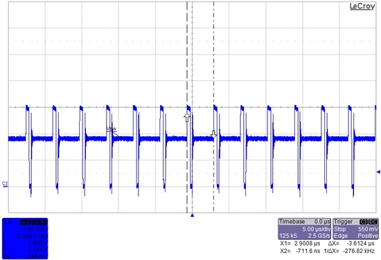
    In addition to above, we would like to know the PFM frequency in case of Vin=3V, Vout=1.8V and Iout=20mA.

    Unfortunately, it seems that the simulation on PFM mode is not supported on neither SwitcherPro nor Webench for this device.

    We thank you once again for your information.

    Best regards,

  • Since you have the EVM, this could be measured under any condition you want.  But here is what I see: 

    Would you be able to share more details about the end application?  You have asked about shutdown current, efficiency, output accuracy, and PFM frequency.  The TPS62740 sounds like a better fit from your questions in all things but accuracy.

  • Hello, thank you for your prompt reply. With regard to your inquiry above, we can send you the detailed information which includes their application information and schematic, but this is a customer proprietary data. I also apologize but the only information that I could disclose here is very limited. Please let me communicate with you directly via e-mail in order to have further proceed. Best regards,