This thread has been locked.

If you have a related question, please click the "Ask a related question" button in the top right corner. The newly created question will be automatically linked to this question.

LM22676, ABNORMAL OPERATION

Other Parts Discussed in Thread: LM22676

Hi people.
             I have one problem with LM22676, in some cases when the chip is unpowered and powered soon after, he not restore to normal operation.

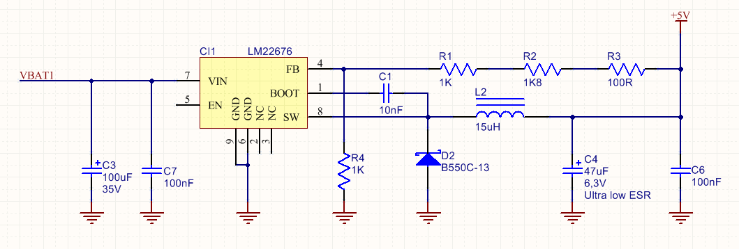
            Describing more clearly: in the attached figure the circuit is powered with 24V, all operation is normal, however when the power is turned off, and reconnected soon after, the LM22676 does not return to the normal operation. The signal in the PIN(8) of LM22676 is absent. The output voltage is 0V.

For the LM22676 to resume operation  is necessary the discharge of the input capacitor(C3)  by a short.

After discharging the capacitor the LM22676o back to normal operation.

 I'm baffled by this behavior, I need the opinion of lords.

Ever seen this situation occur?

  • Hi Davenir,

    Place a reverse biased schottky diode between Vin and Vout. I think the output capacitors are still charged up when you disconnect the supply. This causes the output to discharge through the body diode of the IC and back into the supply thereby confusing the IC. Placing a diode between Vout and Vin should allow a proper discharge path to be present that doesn't include the IC.

    Also, note that for a 24V input, your 100uF cap is probably giving you only 20uF since it derates significantly owing to 35V rating. Likewise for the 47uF =, 6.3V on the 5V output.

    Thanks,

    Anston

  • Hi Anston.
    Your suggestion is plausible. I will implement the diode in the circuit and see the results. I will return with the conclusions.

    Talking of the capacitors of Input and output, you will can suggest best values for the application the input range is 8-32V and the output current is 3A.

    Thanks.

    Davenir Kohlrausch

  • Hi Davenir,

    For input caps, I would suggest 22uF to 47uF with >50V rating if not 50V at a minimum. If finding this becomes difficult, use the next smallest value which will provide the high voltage rating. Sometimes increasing case size can allow higher Voltage ranges to become available.

    For output caps, I would recommend 22uF to 47uF with 25V or 35V. 

    Please leave the bypass caps as is. They are the recommended values.

    Thanks,

    Anston

  • Hi Anston.
    Your suggestion, (The inclusion of one diode between Vout and Vin.) for solve my original problem, showed one good result.

    Another question about this diode suggested. One resistor of low value in Vout between Vout and GND) could show a same result?

    thank you!!!!

  • Hi Davenir,

    I'm glad to hear it. A resistor between Vout to GND is not recommended for multiple reasons, chief among them being very slow response and loss of efficiency/power. 

    The RC delay on the output is not fast enough to discharge the output caps and will cause the body diode to conduct repeating the earlier problem. Any resistor on the output acts as part of the load and will also drop your efficiency and increase power dissipation.

    Thanks,

    Anston