This thread has been locked.

If you have a related question, please click the "Ask a related question" button in the top right corner. The newly created question will be automatically linked to this question.

TPS54618 regulation issue

Other Parts Discussed in Thread: TPS54618

Hi.

I am using this switcher IC for my project which requires 1V, 1.2V, 1.8V and 3.3V power supplies.

The TPS54618 is powered from 5V power supply. 

Except for 3.3V supply all other designs work perfectly. 

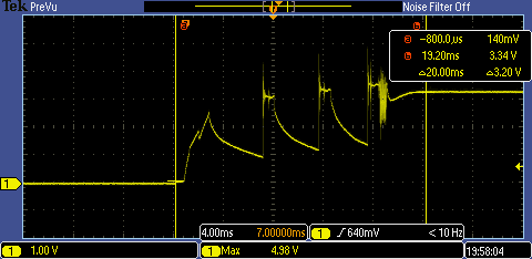
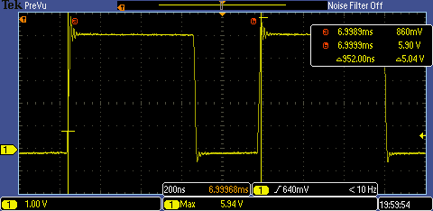
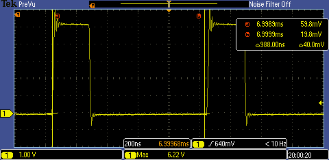
The 3.3V power supply goes out of regulation after multiple turn on and off. If the supply is on and regulated correctly it works without any issue. But when on turn on it fails to regulate then, the supply has huge oscillations.

I am not able to debug where the problem is. Following is the schematics of the power supply.

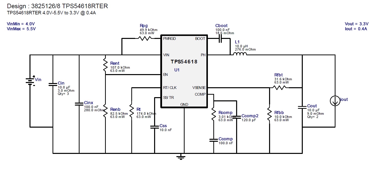
In actual design the Enable pin is connected to Power Good signal from 1.2V power supply and has pull up to 5V.

Also I have changed the inductor value from 10uH to  3.3uH.

Also why the supply does not turn off automatically when it goes out of regulation?

Please help me debug this problem.

Thanks and Best Regards,

Shantanu.

  • Can you post some waveforms in both the good and bad operating states?  Make sure to include the PH node.

  • Hi John,

    Following are the waveform for the 3.3V power supply. I can see that the waveform of Cboot point to Ground is having higher duty cycle compared to other voltage regulation ICs.

    3.3V startup waveform:

    3.3V Cboot waveform:

    Other voltage regulators like 1V, 1.2V and 1.8V have following Cboot waveform

    Please help me to solve the problem.

    Thanks

    Shantanu R Nakhate.

  • the duty cycle of the BOOT voltage will be approx. Vout/Vin so it will be different normally.  The firsrt waveform you posted is Vout = 3.3 V?  I have never seen one like that.  Can you include PH and SS as well?  Also a shot with Vout, COMP and PH?  I'll need to see the same time scale as above as well as a zoomed in plot.  Trigger on one of the falling edges of Vout.  Can you post your actual schematic and PCB layout? 

  • Hi John,

    I think layout is correct. I changes the 1.2V circuit on board which was working well to 3.3V circuit. Also I changed the existing 3.3V circuit to 1.2V circuit.

    Now I powered up the system by supplying the 5V. The new 1.2V circuit worked very fine.

    However the new 3.3V circuit showed same problem.

    I think the problem is in IC. May be the lot is faulty!

    Can you please help me with some results from your end where you have tested the TPS54618 IC for 3.3V output and 5V was supply input.

    Thanks,

    Shantanu Nakhate.

    M:+91 9764552807.

  • I don't normally support TPS54618, but I have a lot of experience with it.  Perhaps someone from that product line can check it.