This thread has been locked.

If you have a related question, please click the "Ask a related question" button in the top right corner. The newly created question will be automatically linked to this question.

ucc28950 delays

Other Parts Discussed in Thread: UCC28950

Hi there,

according to the datasheet of UCC28950, FIG. 7, outF drops after outA. The delay between the two gate signals depends on Tafset (min and max, depending on the voltage at CS pin and adaptive delay settings).

Is it possible that in some configurations outF drops before outA?

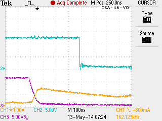
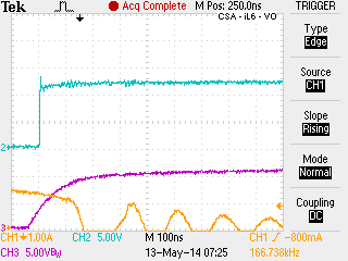
In the attached pictures this is exactly what is happening in my experiments. In yellow is the current of synchronous rectifier E. In blue is the gate signal of Qa and in purple is the gate signal of Qf.

I have Raef(hi)=0 and Raef=70k. Ref is 60k.

Do I have a faulty controller or something is wrong in my design? According to the datasheet this is not the way it should work. As the load current increases, the delay increases and finally outF drops after outA but with a much smaller delay that what I would like.

  •  

    Hello Marco,

    I had done one of these design and found it was much easier to use a fixed delay  approach and not adaptive delays.  Using adaptive delays will only be used to try to remove body diode conduction losses and in most cases the efficiency improvement is not that significant.

    There is an application note on TI's web site that uses this approach.

    http://www.ti.com/lit/pdf/slua560

    There is also an excel design file based on the application note that you can use to modify your design.

    http://www.ti.com/lit/zip/sluc222

    Regards,

  • Hi Mike,

    thank you.

    I have already the design ready and working. I am wandering if the behavior is normal, as according to the datasheet, no matter if adaptive or not, the delay Taf should be positive, meaning outF should fall after outA.

    Can anybody confirm this?

    Thank you